Download
1 / 32
320 likes | 444 Vues
This research paper presents a comprehensive framework for multi-objective synthesis of Network-on-Chip (NoC) topologies aimed at optimizing both system performance and area. The proposed workflow evaluates various NoC architectures and generates Pareto-optimal solutions for effective integration in FPGA prototyping. Key contributions include a novel approach to balance latency and area utilization while facilitating traffic generation using master and slave cores. The results demonstrate a comparative analysis between TLM simulation and FPGA implementation, affirming the efficacy of the synthesis framework.

E N D
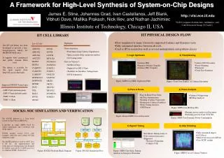
XinyuLI, Omar Hammami Multi-objective Topology Synthesis and FPGA Prototyping Framework of Application Specific Network-on-Chip m5141153 Akram Ben Ahmed
Outline • Introduction • Multi-objective NoC Synthesis Flow • Evaluation results • Summary Research Paper Reading
Introduction • NoC synthesis problem targets to generate NoC topology for different system design objectives such as system performance and area. • Multi-objective NoC synthesis is aimed to optimize the NoC topology and supply Pareto solutions for NoC area and performance. Research Progress Seminar
Introduction • Existing works: • Some focused on single objective synthesis, targeting one parameter without taking care of the remaining ones. • Some were based on multiple objectives synthesis without emphasizing on simulation and execution on FPGA platform. Research Progress Seminar
Outline • Introduction • Multi-objective NoC Synthesis Flow • Evaluation results • Summary Research Paper Reading
Multi-objective NoC synthesis workflow: Basic notions • The application, represented in the core graph, is divided into Master cores (PEs) and Slave cores (memory units). • Routers connecting these cores may have different number of input and output ports.
Multi-objective NoC synthesis workflow: Basic notions • Multi-objective NoC synthesis aims to decide the convenient number of routers needed besides the number of input and output ports for each router. • A maximum number of input output ports is set for each router and should not be exceeded.
Multi-objective NoC synthesis workflow Contains the application communication graph
Multi-objective NoC synthesis workflow: Core graph Slave cores: Memory units Master cores: Processing elements Core graph example a, b, c, d, e, f denote the communication bandwidth
Multi-objective NoC synthesis workflow Generates one initial generation of possible NoC architectures according to parameters
Multi-objective NoC synthesis workflow According to the core graph, TLM traffic generator is generated, which represents the master core with the same throughput and traffic distribution and TLM memory model is used, which represents the slave cores.
Multi-objective NoC synthesis workflow: Traffic generation • According to the core graph Master cores are the responsible for traffic generation and try to communicate with slave cores using OCP IP protocol.
Multi-objective NoC synthesis workflow: Traffic generation Traffic generator: execute a c code for traffic generation
Multi-objective NoC synthesis workflow: Traffic generation sends the traffic throughput and target address through its Master Fast Simplex Link (MFSL) bus interface.
Multi-objective NoC synthesis workflow: Traffic generation Performance onitoring unit: (throughput, average and maximum latency)
Multi-objective NoC synthesis workflow: Traffic generation sends back the monitoring information to the processor
Multi-objective NoC synthesis workflow: Traffic generation Information can be also sent to Host Pc if needed
Multi-objective NoC synthesis workflow The area of each router is obtained from the router library according to their number of input and output ports.
Multi-objective NoC synthesis workflow Verifies whether the solution obtained satisfies the constraints
Multi-objective NoC synthesis workflow: Fitness verification • Performance parameters (Latency, throughput, execution time…) and area fitness are verified. • The maximum number of in-out constraint is also verified.
Multi-objective NoC synthesis workflow: Fitness verification • For each solution violating those constraints, a penalty is added, and then forcing the MOEA to find legal solutions. • The MOEA generates new solutions from the new generation and selects the solution that fits the most to the user objectives.
Multi-objective NoC synthesis workflow Final and optimal Pareto solutions are selected depending on the user objectives
Multi-objective NoC synthesis workflow FPGA prototyping for emulation and validation
Outline • Introduction • Multi-objective NoC Synthesis Flow • Evaluation results • Summary Research Paper Reading
Evaluation results Input Core graph: 8 masters and 4 slaves Research Progress Seminar
Evaluation results 3 Pareto solutions are obtained with TLM simulation (latency and area utilization) Research Progress Seminar
Evaluation results More routers larger area+ lower latency Research Progress Seminar
Evaluation results Less routers smaller area+ higher latency Research Progress Seminar
Evaluation results Comparison between TLM Simulation and FPGA Implementation Research Progress Seminar
Evaluation results • The latency results of TLM simulation and FPGA emulation are different. • The ASIC and FPGA implementation technologies are different. But the relative relationship between the final Pareto solutions rests the same, which means that we can still use TLM simulation to accelerate NoC synthesis, but the final Pareto solution must be validated on RTL. Research Progress Seminar
Outline • Introduction • Multi-objective NoC Synthesis Flow • Evaluation results • Summary Research Paper Reading
Summary • Multi-objective NoC synthesis based on MOEA technology and prototyping workflow is presented. • It offers flexible decisions according to different design objectives and budgets for the designer. Research Progress Seminar