Weld Quality & Weld Testing
Weld Quality & Weld Testing. What is unique about the Eisenhower Interstate Highway System?. One in every 5 miles is straight, this can be used as airstrips in times of war and other emergencies. Each Weldment Should Be: Adequately Designed to meet the intended service for the required life

Weld Quality & Weld Testing
E N D
Presentation Transcript
What is unique about the Eisenhower Interstate Highway System? One in every 5 miles is straight, this can be used as airstrips in times of war and other emergencies
Each Weldment Should Be: • Adequately Designed to meet the intended service for the required life • Fabricated with specified materials and in accordance with the design concepts • Operated and maintained properly
Welds are examined in regard to: • Size • Shape • Contour • Soundness • Other Features as Specified
Welding Code Effect of Discontinuities on Properties • Discontinuities in a welded joint can influence mechanical properties • Codes establish size limits for acceptable discontinuities • Discontinuities unacceptable by a given code are called defects and are subject to repair
Classification of Weld Joint Discontinuities • Welding Process or Procedure Related Discontinuities • Metallurgical Discontinuities • Design Related Discontinuities
Classification of Weld Joint Discontinuities Welding Process or Procedure Related Discontinuities • Other • Arc Strikes • Slag Inclusions • Tungsten Inclusions • Oxide Films • Spatter • Arc Craters • Geometric • Misalignment • Undercut • Concavity or Convexity • Excessive Reinforcement • Improper Reinforcement • Overlap • Burn-through • Backing left on • Incomplete Penetration • Lack of Fusion • Shrinkage • Surface Irregularities
Classification of Weld Joint Discontinuities Metallurgical Discontinuities • Cracks or Fissures • Hot • Cold or Delayed • Reheat • Stress-Relief • Strain-age • Lamellar Tearing Heat-Affected Zone Microstructural Alterations Weld Metal & HAZ Segregation • Porosity • Spherical • Elongated • Worm-hole Base Plate Laminations
Classification of Weld Joint Discontinuities Design Related Discontinuities Changes in Section & Other Stress Concentrators Weld Joint Type
Supplemental Work Open the web page under “Demonstrations” and do the exercise entitled “Discontinuities http://www-iwse.eng.ohio-state.edu/we300/Discontinuity/discontinuity.aam
Supplemental Work Pages 364 through 367 of the Welding Handbook list table of Common Causes and Remedies like the one on the Right. Review these tables to gain insight about Discontinuities
Questions? • Turn to the person sitting next to you and discuss (1 min.): • From a general point of view, how would you rank the following discontinuities in their severity to weld properties: Hot Cracks, Change in section size, Porosity, ? Why
Welding Discontinuities Porosity • Porosity is the entrapment of small volumes of gas in solidifying weld metal • Prevention • Drying consumables • Cleaning, degreasing material being welded • Electrode or filler metals with higher level of deoxidants • Sealing air leaks, reducing excess shielding gas flow 0.1.1.4.2.T7.95.12
Welding Discontinuities Slag inclusions • Slag inclusions are irregularly shaped, not spherical like porosity • Prevention • Position work and/or change electrode/flux to increase slag control • Better slag removal between passes • Dress weld surface smooth if it is likely to cause slag traps • Remove heavy mill scale on plate 0.1.1.4.2.T8.95.12
Welding Discontinuities Lack of Fusion • Lack of fusion is caused by incorrect welding conditions • Prevention • Procedure for complete fusion should be verified by testing • Increased energy input • Correct electrode angle and work position 0.1.1.4.2.T9.95.12
Welding Discontinuities Incomplete Root Penetration • Incomplete root penetration can be caused by • Excessively thick root face, insufficient root gap • Incorrect welding conditions • Misalignment of second weld • Prevention • Improved joint preparation • Test weld verifications for correct parameters • Reassessment of back gouging 0.1.1.4.2.T10.95.12
Welding Discontinuities Overlap • Overlap is an imperfection at the weld toe or root caused by metal flowing onto the surface of the base metal without fusing to it • Prevention • Adjust electrode manipulation to ensure fusion of base metal • Limit size of fillet to 9-mm leg length 0.1.1.4.2.T11.95.12
Welding Discontinuities Undercut • Undercut is an irregular groove at the weld toe in the parent metal or previous pass caused by • excessive weaving • melting of top edge of fillet weld with high current • Prevention • Weld in flat position • Change shielding gas to one which produces better wetting • Terminate welds so they don’t finish at a free edge 0.1.1.4.2.T12.95.12
Welding Discontinuities Excessive Penetration • Excessive penetration is caused by • Incorrect assembly or preparation • Edge preparation too thin to support weld underbead • Excessive root gap • Energy input too high • Lack of operator skill • Prevention • Control of preparation, backing bars 0.1.1.4.2.T13.95.12
Welding Discontinuities Root Concavity • Root concavity is caused by • Excessively thick root face • Insufficient arc energy for penetration • Excessive backing gas pressure • Prevention • Reduce root face thickness, control backing gas pressure • Establish a procedure by test welding 0.1.1.4.2.T14.95.12
Welding Discontinuities Spatter • Spatter consists of small droplets of electrode material that land beside the weld and may or may not fuse to the base material • Prevention • Reduce energy input • Shorter arc length • Reposition current return clamp to reduce magnetic arc blow or switch to AC current 0.1.1.4.2.T15.95.12
Questions? • Turn to the person sitting next to you and discuss (1 min.): • We have just looked at a list of discontinuities and preventative measures. How does this information effect the opinions of people involved in writing codes for proper welding conditions?
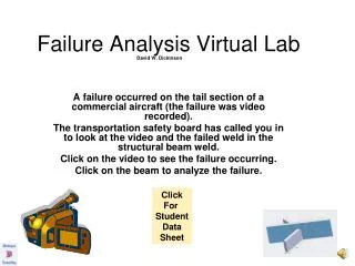
Fatigue Design Fatigue Appearance • Distinct fracture surface has a characteristic texture • Concentric line pattern • Smooth portion referred to as clamshell texture multiple initiation sites