Design for Accelerator Reliability
Design for Accelerator Reliability. Paolo Pierini, Daniele Sertore INFN Sezione di Milano LASA paolo.pierini@mi.infn.it daniele.sertore@mi.infn.it. Intro. The material here is largely inspired by work that is being done in the context of several ADS studies TRASCO/ADS studies in Italy

Design for Accelerator Reliability
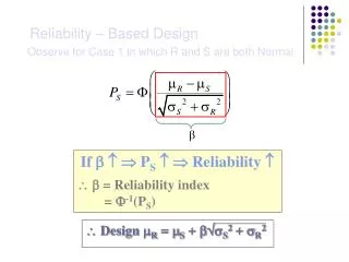
E N D
Presentation Transcript
Design for Accelerator Reliability Paolo Pierini, Daniele Sertore INFN Sezione di Milano LASA paolo.pierini@mi.infn.itdaniele.sertore@mi.infn.it
Intro • The material here is largely inspired by work that is being done in the context of several ADS studies • TRASCO/ADS studies in Italy • PDS-XADS (EU) FP5 Programme • WP3 (Accelerator) participants: Framatome, Ansaldo, CEA, CNRS, U.Frankfurt, ENEA, INFN, ITN, IBA, FZJ • OECD/Nuclear Energy Agency Working Party on Partitioning and Transmutation • International Working Group on Accelerator Reliability • Important references can be found in Proceedings of the Accelerator Reliability Workshop (ARW) held in Grenoble in 2002 • P.D.T. O’ Connor “Practical Reliability Engineering”, Wiley TESLA Meeting
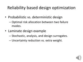
Overview • Limits of reliability mathematics • An accelerator system is way too complex for accurate predictions • Design strategies • Component Derating (a.k.a. overdesign) • Redundancy (spares on line) • Fault Tolerance (most important) • Reliability database considerations • Can we set up a meaningful DB of accelerator components? • Reliability predictions: FMEA • What can be done to assess critical areas in the design without knowing too many details of each component and their relative functional connections • The use of formal methodologies for reliability/availability assessment (top-down, through use of a database of components) requires • Use of established components (!) • Detailed information on component connection and location (!) • Failure Mode and Effect Analysis (bottom-up) TESLA Meeting
Warning/1 • Reliability engineering is a technical discipline for • estimating, • controlling and • managing the probability of failures • in complex systems. • However, for most systems, due to the technical complexity of the design, it is not enough to specify and allocate the reliability of components in order to predict accurately the reliability of the system TESLA Meeting
Warning/2 • Formal mathematical and statistical methods can be applied to measure and assess reliability characteristics of components, but the associateduncertainties are high, leading to reliability estimates with limited credibility • “(...) the role of mathematical and statistical methods in reliability engineering is limited, and appreciation of the uncertainty is important in order to minimize the chances of performing inappropriate analysis and of generating misleading results. (…) practical engineering must take precedence in determining the causes of problems and their solutions” [PDT O’Connor] TESLA Meeting
However… • There exist design principles to achieve a reliable system: • Derating: Operate components below max rating • Redundancy: Provide more components with a given function • Fault Tolerance: Component failure do not imply system failure • Mathematical and statistical methods for reliability assessment teach us that the reliability of a complex system depends • not only by the component specifications (MTBF/MTTR), • but also, even more importantly, by the logical and functional connections (role of redundancies and spares) • In other words, proper planning of redundancies allows building reliable systems out of moderately reliable components TESLA Meeting
Prob.Densityfunction Load Strength Design/1: Derating • Derating (and Load/Strength considerations) • Standard procedure in all EEE (electrical, electronic and electromechanical) & mechanical designs • Handles batch variation of components • Ensures that marginal devices do not cause system failures • But: no rigid rules exists for derating factors • Not always clear the benefit on MTBF (linear law?) Ideal situation TESLA Meeting
Prob.Densityfunction Strength Load Design/1: Derating • Derating (and Load/Strength considerations) • Standard procedure in all EEE (electrical, electronic and electromechanical) & mechanical designs • Handles batch variation of components • Ensures that marginal devices do not cause system failures • But: no rigid rules exists for derating factors • Not always clear the benefit on MTBF (linear law?) Load-Strengthinterference, to be avoided by setting safety margins TESLA Meeting
Design/2: Redundancy • Redundancy • Different strategies can be followed for standby redundancy • Hot (failure rate standby = failure rate operating) • Warm (failure rate standby < failure rate operating) • Cold (failure rate standby = 0) Component Component Component Hot Standby Warm/Cold Standby Switch The switch reliability and contribution to MDT need to be carefully included in the reliability assessment Parallel system TESLA Meeting
Design/3: Fault Tolerance • Fault Tolerance • Implies a bottom-up approach for the assessment of each component fault on the system operation • The most difficult and time consuming feature to assess with precision for the accelerator operation • Plenty of technological issues • Complex hierarchy of dependent subsystems • Interaction with beam physics issues (not all cavities or quadrupoles have the same effects, depending on their relative positions in the beamline, even when considering identical objects under identical operating conditions) • Need extensive beam dynamics simulation scenario, transforming component faults into their effects (if any) on the particle beam (e.g. no field in cavity, bad field in magnet, etc.) TESLA Meeting
Fault Tolerance • The control system plays a major role in guaranteeing fault tolerance to the accelerator • Fault tolerance requires at least five necessary functions: • Fault detection • It happened! • Fault isolation • why did it happen? • Fault containment • avoid fault propagation • next weakest link effect • common cause failures • Fault masking • no spurious value on system state due to a faulty component is passed out of the system boundary as representative of the system state • Fault compensation • Capabilities to compensate functions of the faulty component with the use of redundant components TESLA Meeting
Component Database • Credibility of input data is one of the most serious issues when performing accelerator reliability and availability analysis, applying current methods and tools • credible failure and repair rates, especially for one-of-a-kind large complex system such as an accelerator facility, are not readily available • While it is possible to use the reliability theory to model accelerator systems, there does not exist, up to now, a formal reliability database for accelerator components available, leading thus to large uncertainties in the results TESLA Meeting
Component Database/2 • At each accelerator laboratory large datasets of information are regularly collected about the failures occurred • All these data are not actually organized in a consistent database, and preliminary estimations on the manpower required for their organization and harmonization has, until now, slowed all the efforts directed in this sense • Minor caveat (from Y.Cho slides at TESLA Collaboration Meeting in Daresbury, 2002) • During design stages of the APS, we have studied log books of several laboratories (CERN, FNAL and Cornell) to collect pertinent data. • Due to lack of uniformity in log keeping, it was difficult to combine data from various laboratories in components of subsystem basis – i.e. difficult untangle components of rf system TESLA Meeting
Side note on MTTR • It is also important to note that the MTTR of the system components needs to take into account • not only the repair time itself, • but also all the time needed • for fault detection and identification, • any time needed before accessing the component (e.g. radiation decay times if components are located in a protected area), • time to bring the spare part in position, • and finally the time for system restart and revalidation • All these times may be substantially longer than the repair time and strongly depend on the whole system layout • MTTR data taken out of its context can be very misleading TESLA Meeting
Nature of connections is important • Not only the component specifications (in terms of MTBF & MTTR which can be relatively easily collected in a DB) are important for the reliability assessment of the system • The logical or functional connection between components plays a major role in reliability mathematics • Series connection • Parallel connection • Hot, warm and coldredundancy • k out of n redundancy • Also, in our case we may have both repairable and non-repairable systems during the mission time • E.g. 2-tunnel accelerator scheme (main linac + service tunnel) • Pay attention to common cause failures TESLA Meeting
Accelerator components • Accelerator components are found in two categories: • “Industrial” components • e.g. cooling, vacuum, cryogenics, electrical power supplies • Data is available from other areas of application (e.g. fission/fusion, aerospace industry or available information from research organizations or companies) • Special accelerator components • e.g. RF cavities, klystrons, optics components, etc. • Reliability parameters are inferred on the basis of information available • from vendors • from previous studies (where applicable), • from existing facilities operational data analysis • for most of them a sort of engineering/expert judgment is envisaged in order to reach an appropriate evaluation, suitable for the reliability analysis TESLA Meeting
Operating considerations • The reliability goal is defined for a specific accelerator operation (mission time) and maintenance scenario • To meet reliability and availability specifications (and keep them during time) maintenance and spare parts policies needs to be set up • In existing accelerator facilities (for physics) short and frequent maintenance periods are scheduled • For the ADS, the maintenance policy needs to be compatible with the fuel cycle, and • Either adequate redundancy must be planned • Or access to devices failing frequently (e.g. power supplies in separate tunnel, with free access) • Always plan to avoid the infant mortality and wear out decrease in reliability of components (bath tub curve) TESLA Meeting
Reliability and Availability design • The extreme case – ADS (Waste Transmutation) Goals • Nominal proton beam: CW, 6 mA, 600 MeV • Few beam stops a year > ~1s • Unlimited number of short interruptions < ~1s • These tight requirements necessary imply • Very efficient failure detection means, i.e. • Extensive diagnostics capabilities • Strategies to maintain accelerator operation within nominal parameters when a fault is detected, before intervention of safety interlocks (i.e. Fault Tolerance) TESLA Meeting
Reference Configuration • The first step in any reliability analysis requires the description of a reference configuration of the accelerator system • Identification of large functional blocks or large facilities (needing buildings or areas physically separated with respect to the linac) • Need of a “naming scheme” (WBS: Work Breakdown Structure) TESLA Meeting
1 Accelerator 1.1 Ion Source 1.2 LEBT 1.3 RFQ 1.4 MEBT 1.5 Low Energy Acc. [nc & sc] 1.6 Spoke Linac - Low b 1.7 Spoke Linac - High b 1.8 Elliptical Linac - Low b 1.9 Elliptical Linac – Med. b 1.10 Elliptical Linac - High b 1.11 HEBT 1.12 BDS to Target 2 Cryogenics 2.1 Cold Box 2.2 He Distribution System 2.3 2 K pumping system 2.4 He recovery system 3 Services 3.1 Water System 3.2 Compressed ai 3.3 Electrical Power 4 Controls ADS Work Breakdown Scheme • WBS hierarchy for subsystems is omitted here (…) TESLA Meeting
Services and Support Systems • Assumptions on service/support systems reliability/availability can be made on the basis of similar large existing facilities (e.g. CERN, DESY, TJNAF, KEK, FNAL, ESRF, …) • Example (ARW, C. Commeaux): experience of large cryoplants is excellent • KEK 137,000 h operation, after “childhood”, A=99.2% • FNAL 76,000 h, A=99.5% • CERN 120,000 h, A=99.3% • HERA, A=99.3 % TESLA Meeting
Prediction Methodologies • Top-Down / Deductive • Need detailed info about components and connections • Need “solid” database of components • Most common: Reliability Block Diagram (RBD) • Layout of RBD usually depends on system state! • Fault Tree Analysis (FTA) • Determine all component faults that lead to given system fault • Methods for availability allocation and maintenability • Integrated Logistic Support (ILS) • Logistic Support Analysis (LSA) • Bottom-Up / Inductive • Failure Mode and Effects (Criticality) Analysis (FMEA/FMECA) • Can be performed with expert judgment on relative criticality of components • Can be performed also with less detail in design TESLA Meeting
FMEA & Tables • FMEA needs to perform the following tasks • Identification of possible failure modes of each component • Listing of all the envisaged faults • Analysis of the effects of the component fault on the performance of the overall system (or at different levels in the system tree) • Identification of suitable preventive and corrective actions concerning the accident (or possible mitigating factors) • Severity ranking of the faults • Possibly, relative frequency of faults occurrence • All the collected data needs to be gathered in the fault assessment tables. • Standard format for the FMEA TESLA Meeting
Info 1: Description • WBS #:The reference of the item in the WBS list • Item: The name of the component/subcomponent (from the WBS) • Function: A short description of the component function • Failure mode: A description of the fault under consideration TESLA Meeting
Info 2: Causes/Prevention • Cause: A possible cause for the fault under consideration • Preventive actions on cause: Possible preventive strategies in order to avoid the fault cause (e.g. redundancy, preventive maintenance, etc.) TESLA Meeting
Info 3: Effects/Ranking • Failure effects: Description of the consequences, in three levels, of the fault under consideration (severity ranked in a standardized way) • Local:Consequences on the local system (e.g. inoperative, reduced capabilities, etc.) • Next higher level:Consequences on the system to which the component under consideration belongs • Effects on beam delivery:Consequences on the beam delivery to target TESLA Meeting
Info 4: Detection • Failure detection symptoms: Existence of possible symptoms that leads to the detection of the fault under consideration • Failure detection means: Kind of signal used to detect the failure (e.g. acoustic noise, temperature sensor, electrical signal, …) TESLA Meeting
Info 5: Correction • Corrective actions on consequences: What can be made to correct the failure (e.g. replace with beam on, replace at next maintenance, shutdown beam and replace) • Comments: Any additional useful information TESLA Meeting
Fault assessment table TESLA Meeting
Severity Ranking Tables TESLA Meeting
Example: Cryomodule From: PDS-XADS WP3 Nice Meeting Jan 2003 (D. Sertore, INFN) TESLA Meeting
WBS location • Accelerator … 1.8 Elliptical Linac - Low beta section 1.8.1 Cryomodule 1.8.1.1 RF Cavities & ancillaries 1.8.1.2 RF Coupler 1.8.1.3 Cold connections 1.8.1.4 Electrical connections 1.8.1.5 Insulation Vacuum systems 1.8.1.6 Diagnostics devices 1.8.2 RF System 1.8.3 Magnets system 1.8.4 Diagnostics devices 1.8.5 Beam Vacuum System 1.8.6 Cryogenic System 1.8.7 Protection and local control system … TESLA Meeting
Leaks are small! 1.8.1.1 RF Cavities and Ancillaries Possible Vacuum failures: Insulation to Beam Helium to Beam Air to Beam Helium to Insulation TESLA Meeting
Loss is due to a very large leak !!! 1.8.1.1 RF Cavities and Ancillaries Fast (piezo) Tuner Failure For microphonics TESLA Meeting
1.8.1.1 RF Cavities and Ancillaries Slow Tuner Failure RF Failures TESLA Meeting
Conclusions • Component data has only a limited role on system reliability, nature of connection is important! • The FMEA analysis is a useful tool for: • Assessing reliability critical areas in the design • Planning how to deal with component faults and providing fault tolerance • Revising component design in order to minimize probability of occurrence of faults • Develop a Fault Tree Analysis (gathering all component events that lead to a system event) • The identification of failure modes is based on experience (expert judgement) and on critical analysis of existing (similar) hardware components TESLA Meeting