Download
1 / 38
410 likes | 760 Vues
EE40 Lec 15 Logic Synthesis and Sequential Logic Circuits Prof. Nathan Cheung. 10/20/2009 Reading: Hambley Chapters 7.4-7.6 Karnaugh Maps: Read following before reading textbook http:// www.facstaff.bucknell.edu/mastascu/eLessonsHTML/Logic/Logic3.html. Synthesis of Logic Circuits.

E N D
EE40 Lec 15Logic Synthesis and Sequential Logic Circuits Prof. Nathan Cheung 10/20/2009 Reading: Hambley Chapters 7.4-7.6 Karnaugh Maps: Read following before reading textbook http://www.facstaff.bucknell.edu/mastascu/eLessonsHTML/Logic/Logic3.html
Synthesis of Logic Circuits Suppose we are given a truth table for a logic function. Is there a method to implement the logic function using basic logic gates? • Answer: There are lots of ways, but one way is the • “sum of products” (SOP) method: • Write the sum of products expression based on the truth table for the logic function • Implement this expression using standard logic gates. • An alternative way is the “product of sums” (POS) method.
Logic Synthesis Example: Adder S1= carry, So=sum Truth Table of Adding Three Inputs : A, B, and C
Logic Synthesis Example: Adder • Sum-of-products method for S1 • Find rows where S1 is 1 • Write down each product of inputs which create a 1 (invert logic variables that are 0 in that row) • Sum all of the products • Draw the logic circuit Input Output A B C A B C A B C A B C A B C + A B C + A B C + A B C
Logic Synthesis Example: Adder A SOP Logic Circuit B C A B C A A B B C A B C + A B C + A B C + A B C C
Creating a Better Circuit What makes a digital circuit better? • Fewer number of gates • Fewer inputs on each gate • multi-input gates are slower • Let’s see how we can simplify the sum-of-products expression for S1, to make a better circuit… • Use the Boolean algebra relations
Logic Synthesis Example: Adder A B C A B C A SOP Simplification B Can we simplify this digital circuit further?
Logic Synthesis Example: Adder Add in two inversions (signal stays the same) A B C A B C A B
Logic Synthesis Example: Adder A This becomes a NAND B C A B C A Apply DeMorgan’s Theorem, i.e. “bubble pushing” B
NAND Gate Implementation • De Morgan’s law tells us that is the same as • By definition, is the same as • All sum-of-products expressions can be implemented with only NAND gates.
Logic Synthesis Example: Adder Output Input • Product-of-sums method for S1 • Find rows where S1 is 0 • Write down each sum of inputs which create a 0 (invert logic variables that are 1 in that row) • Product of the sums • Draw the logic circuit
SOP or POS ? The Boolean Expression will appear shorter • If the Truth table has less 1’s, SOP • If the Truth Table has less 0’s, POS • After Minimization, both methods should give same results , unless there are “don’t care” rows in the Truth Table.
Notations of Hambley Textbook Sum of Products (SOP) Product of Sums (POS)
Another Logic Synthesis Example: XOR Product of Sums (POS) Sum of Products (SOP)
Karnaugh Maps 2-variable Karnaugh Map 3-variable Karnaugh Map 4-variable Karnaugh Map * Arrows show example locations of logic PRODUCTS
Comments on Karnaugh Maps • Required reading • http://www.facstaff.bucknell.edu/mastascu/eLessonsHTML/Logic/Logic3.html • You may find more details there than the textbook. • As the number of variables increases (say >4) it becomes more difficult to see patterns, and computer methods start to become more attractive. • EE40 will focus only on 3 variables and 4 variables Karnaugh Maps
Comments on Karnaugh Maps For a 4-variables map • 1-cube: 1 square by itself • ( logic product of 4 variables) • 4-cube: 4 squares with common edges • ( logic product of 2 variables) • 2-cube: 2 squares that have a common edge • ( logic product of 3 variables) • 8-cube: 8 squares with common edges • ( logic product of 1 variable)
Comments on Karnaugh Maps • In locating cubes on a Karnaugh map, the map should be considered to fold around from top to bottom, and from left to right. • Squares on the right-hand side are considered to be adjacent to those on the left-hand side. • Squares on the top of the map are considered to be adjacent to those on the bottom. • Example: The four squares in the map corners form a 4-cube CD 00 01 11 10 00 01 AB 11 10
4-Variables Example • From Truth Table and Sum of Products F= m(1,3,4,5,7,10,12,13) • Converting the row numbers to binary yields 0001,0011, 0100 etc.. • Place 1’s into the Karnaugh Map
3-Variables Example: Adder B Input Output Simplification of expression for S1: BC A C BC AC AB S1 = AB + BC + AC
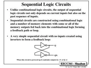
Sequential Logic Circuits • Sequential logic circuits that possess memory because their present output value depends on previous as well as present input values.
Clock Signals • Often, the operation of a sequential circuit is synchronized by a clock signal : • The clock signal regulates when the circuits respond to new inputs, so that operations occur in proper sequence. • Sequential circuits that are regulated by a clock signal are said to be synchronous. vC(t) positive-going edge (leading edge) negative-going edge (trailing edge) VOH time 0 TC 2TC
Flip-Flops • One of the basic building blocks for sequential circuits is the flip-flop: • A simple flip-flop can be constructed using two inverters: Q Two possible states: Q * Circuit can remain in either state indefinitely
The S-R (“Set”-“Reset”) Flip-Flop • Rule 1: • If S = 0 and R = 0, Q does not change. • Rule 2: • If S = 0 and R = 1, then Q = 0 • Rule 3: • If S = 1 and R = 0, then Q = 1 • Rule 4: • S = 1 and R = 1should never occur. S Q S-R Flip-Flop Symbol: R Q
Realization of the S-R Flip-Flop S Q Q R
Clocked S-R Flip-Flop • When CK = 0, disables the inputs R and S • When CK = 1, enables inputs R and S
The D (“Delay”) Flip-Flop • The output terminals Q and Q behave just as in the S-R flip-flop. • Q changes only when the clock signal CK makes a positive transition. D Q D Flip-Flop Symbol: CK Q
D Flip-Flop Example (Timing Diagram) CK t D t Q t
Registers • A register is an array of flip-flops that is used to store or manipulate the bits of a digital word. • Example: Serial-In, Parallel-Out Shift Register using D Flipflops Q0 Q1 Q2 Parallel outputs Data input D0 Q0 D1 Q1 D2 Q2 CK CK CK Clock input
Shift Register Timing Diagram
Conclusion (Logic Circuits) • Complex combinational logic functions can be achieved simply by interconnecting NAND gates (or NOR gates). • Logic gates can be interconnected to form flip-flops. • Interconnections of flip-flops form registers. • A complex digital system such as a computer consists of many gates, flip-flops, and registers. Thus, logic gates are the basic building blocks for complex digital systems.