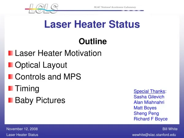
Laser Heater Status
Outline Laser Heater Motivation Optical Layout Controls and MPS Timing Baby Pictures. Laser Heater Status. Special Thanks : Sasha Gilevich Alan Miahnahri Matt Boyes Sheng Peng Richard F Boyce. Motivation.

Laser Heater Status
E N D
Presentation Transcript
Outline Laser Heater Motivation Optical Layout Controls and MPS Timing Baby Pictures Laser Heater Status Special Thanks: Sasha Gilevich Alan Miahnahri Matt Boyes Sheng Peng Richard F Boyce
Motivation The LCLS injector system will incorporate a laser-electron-beam heater system (an inverse free electron laser) in order to generate an uncorrelated energy spread in the electron beam [1]. This produces Laudau damping in the bunch compressor chicanes in order to suppress potential micro-bunching instabilities that may be driven by Coherent Synchrotron Radiation (CSR) in the bunch compressors, and Longitudinal Space Charge (LSC) forces in the linac. The laser-heater system is shown in Fig. 1. The heater system is located just downbeam of the L0b accelerator section at 135 MeV in the off-axis LCLS injector housing. _________________________________________________________ PRD 1.2-004-r2
Laser Heater Requirements Laser Heater Beam Parameters (ESD 1.2-122)
Laser Heater Optical Transport Rack location LKA-03 Transport Lines Mirror Laser Heater Rack location LIT-01
Layout of the Laser Heater Optical System in the Laser Lab Waveplate & polarizer PC & polarizer Pulse Stretcher 3 lens Telescope Shutter PH1 PH2 Streak camera Energy control UV beam UV Conversion Unit To vertical transport tube IR Laser System Path Length Adjuster
Layout of the Laser Heater Optical System in the Injector Vault We had to put in additional lens to get the required beam size Transport to the Tunnel OTR MH4 Transport to the LH Shutter VHC PD WP MH3 MH4, MH3, MH2 - Motorized mirrors Waveplate and polarizer in front of both cameras MH2 PH3 CH1
Fast Energy Control – Pockels Cell and polarizer Inrad - PKC02-SG20 : KD*P Dual Crystal Pockels Cell, with AR coated windows, with sol-gel coated crystal - Aperture 20mm Slow Energy Control – Waveplate and polarizer Energy Control
In the Laser Lab Two powermeters – beam energy out of the laser / after the attenuator Streak camera – temporal diagnostics Camera – beam shape - optional In the injector Vault - Upstream of the undulator Camera VHC – virtual heater (spatial shape and position of the laser beam) Powermeter Downstream of the undulator Photodiode for timing adjustment OTR screens Diagnostics
Before the undulator vacuum chamber was installed a camera was palced on a rail, which was aligned to the undulator axis Aligned the laser beam so that it was centered on the camera at any Z-position Beam was centered on the cameras VHC and CH1 We adjusted the Z-position of the VHC so that the beam size on the camera is the same as in the center of the undulator Alignment
Adjustment of LH2 position for the beam size Coarse adjustment of LH3 position to collimate the beam Precise adjustment of LH3 position for the minimum beam size in the center of the undulator Alignment of the telescope for the required beam size and waist position in the LH LH1 LH2 LH3 Telescope
Precise alignment of the telescope lens LH3 for waist position Alignment is manual
Beam in the Undulator Center and VHC Undulator Center VHC
Beam on the OTRs OTR1 OTR2
Piece of OTR foil was placed on the OTRH1 location and illuminated by the laser beamfor about 3-5 min (beam rms was about 320um). There was small damage at the energy 7uJ. At the beam energy 2.3uJ we did not see any damage. We will put flipper filter to attenuate the laser beam below 2uJ (at min setting of the energy control units) When the filter goes out, a blank plate will go in OTR Damage Threshold
Photodiode ET-2030 in the output beam Oscilloscope to watch a PD signal – in the Laser lab Additional attenuation of the laser beam might be required Laser Beam Timing Photodiode ET-2030 spec
Laser Room Energy Control: Waveplate Pockel Cell with Pulse to Pulse DAC control (Required by March) Energy Measurement: Coherent EPM 2000 Power meter 2 Sensors with Rotation Stages MPS Shutter Injector Vault Laser Steering Feedback 4 Actuators 2 Cameras (CH1 and VHC) 2 Waveplates for Camera Intensity Control Energy and Time Measurements: Photodiode Coherent LabMax-TOP Power meters (verified as BSA compatible) Virtual Heater Camera (VHC) adjustment 2 Actuators 2 OTRs MPS Laser Attenuator Photodiode Shutter Laser Heater Required Control Items
Extension of existing Drive Laser System Use existing IOCs Few new types of devices LabMax-Top Power Meter Verified to be BSA compatibility Analog Output for beam rate measurement Will use slow RS-232 communication for configuration and advance features Laser Heater MPS Shutter Pockel Cell Driver with DAC control Software
Drive Laser EDM Display Change Between Systems
Change Between Systems Heater EDM Display
MPS protection for OTR screens and photodiode. MPS Logic: MPS Shutter blocks IR Laser beam IF Beam is not attenuated by Laser Attenuator AND OTRH1 and OTRH2 are not out OR Photodiode is unprotected by photodiode shutter Machine Protection
No steering feedback loop upstairs Feedback loop downstairs should take care of the small beam motions Large beam shift can cause clipping on the flipper filter, lens or tube windows Multiple reflections on the cameras Replace tube windows with coated ones Possible Issues
Before Laser heater here Courtesy of Paul Emma
Optical LH system installed After Laser heater here
All transport tubes are connected Turbo pump upstairs Ion pump downstairs Transport tubes in the vault
Motorized mirror MH4 (open loop) Focusing Lens Flipper with a filter to protect OTR (not in yet) Optics inside the ceiling box LH horizontal tube UV beam tube
Laser Heater Table in the Vault MH3 VHC on motorized XY stage CH1 WP VHC To powermeter WP CH1 MH2
Laser Heater Table in the Vault From MH2 Waveplate To VHC 50% beamsplitter MH1