Download
1 / 32
390 likes | 1.18k Vues
Learn about the chemical machining process, its stages, applications, advantages, and disadvantages. Discover how chemical milling reduces weight in aerospace components and enables precise metal removal. Explore Electrochemical Machining (ECM) and its application in producing intricate shapes. Dive into the principles of material removal through controlled chemical reactions in chemical engraving.

E N D
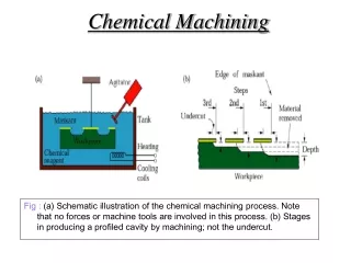
Chemical Machining Fig : (a) Schematic illustration of the chemical machining process. Note that no forces or machine tools are involved in this process. (b) Stages in producing a profiled cavity by machining; not the undercut.
Steps in Chemical Machining • Cleaning ‑ to insure uniform etching • Masking ‑ a maskant (resist, chemically resistant to etchant) is applied to portions of work surface not to be etched • Etching ‑ part is immersed in etchant which chemically attacks those portions of work surface that are not masked • Demasking ‑ maskant is removed
Chemical Machining • In this process, metal is removed from the work piece through a controlled chemical attack or etching. Metal can be removed from selected portions or from entire surface of the work piece, according to requirement. • Chemical machining involves the use of acids or alkali solution ( chemical ) known as enchant to etch away unwanted material, leaving final desired pattern or part. • Principle of operation : As this is a controlled dissolution of work material in a Chemical ( etchant ), the portion that need no machining is to be covered ( protected ) by applying a mask on work surface known as resist ( maskant ). • The work material is then submerged in a hot chemical solution and erosion of unprotected area takes place. After machining , masking material is removed from the surface of work piece and part is cleaned and inspected . • The basic function of etchant is to convert a material ( metal ) into a metallic salt that can be dissolved in the etchant ( chemical ) and thus metal is removed from the work surface. • Common etchants are HNO3 FeCl3 . Different etchants are used for different material . • Common maskants ( resists ) are vinyl , neoprin rubber , butyl base material, which are applied to work piece by flow , dip or spray coating.
Chemical machining - Applications Chemical attacks metals and etch them by removing small amounts of material from the surface using reagents or etchants Fig : (a) Missile skin-panel section contoured by chemical milling to improve the stiffness-to weight ratio of the part. (b) Weight reduction of space launch vehicles by chemical milling aluminum-alloy plates. These panels are chemically milled after the plates have first been formed into shape by processes such as roll forming or stretch forming. The design of the chemically machined rib patterns can be modified readily at minimal cost.
Chemical Machining Advantages : 1. Tooling cost is very low 2. It is flexible process from the design point of view, 3. Extremely thin materials are machinable without the help of work holding device . 4. Production of stress free and crack free surfaces. 5. Both faces of the work piece can be machined simultaneously Disadvantages : 1. low metal removal rate , hence slower process. 2. Sharp corners can not be produced. 3. High manufacturing cost
Chemical milling: • Shallow cavities produced on plates, sheets, forgings, and extrusions. It is used for metal removal from thicker work piece using screen resist type maskants. • Chemical blanking ( photochemical machining / blanking) • Modification of chemical milling • Material removed from flat thin sheet by photographic techniques ( using photo resist type maskants ) • It is used for metal removal of thin electronic and computer metallic components. Burr free etching of printed-circuit boards, decorative panels, thin sheet metal stampings as well as production of small and complex shapes Chemical Engraving : It is used for special precision contoured reproduction
Electro Chemical Machining ECM Reverse of electro-plating (workpiece is anode) Fig : Schematic illustration of the electrochemical-machining process. Cathode hollow Anode NaCl Shaped tool made of brass , copper , bronze , or stainless steel Tool face has the reverse shape to be made on the work piece.
Electrochemical Machining (ECM) • Electrical energy used in combination with chemical reactions to remove material • Reverse of: electroplating • Work material must be a: conductor • Feature dimensions down to about 10 μm Material removal by anodic dissolution, using electrode (tool) in close proximity to work but separated by a rapidly flowing electrolyte
Electrochemistry of ECM (Cu ) anode Cathode work piece ( Fe ) Electroplating Instead of CuSO4 , if we use NaCl as a electrolyte , then salt is not consumed along with the process , it only act as a carrier of current.
Electrochemistry of ECM cathode anode W/P W/P 7.5 V 0 V W/P W/P 15 V 30 V
Let us consider aqueous solution of NaCl + H2O as a electrolyte. When voltage difference is applied , across the electrode , reactions At cathode and anode are Fe Fe ++ + 2 e( At anode ) 2H2O + 2 e H2 + 2 ( OH ) -( At cathode ) The positive metal ions tend to move towards cathode and negative hydroxyl ions are attracted towards the anode . Thus positive metal ions combine with negatively charged ions to form ferrous oxide as Fe ++ + 2 ( OH ) - - - Fe ( OH )2 This ferrous oxide forms an insoluble precipitate , so in this anode ( work piece ) dissolves and only H2 gas is formed at the cathode , leaving shape of cathode ( tool ) unchanged , i.e. there is no Deposition on tool . Therefore electrolyte should be chosen in such a way that no deposition at either electrode takes place. Electrochemistry of ECM
Electrochemical machining • It is based on Faraday’s law of electricity. • Electrolyte acts as current carrier i.e. conduction of electricity is achieved through movement of ions existing in the electrolyte • As the power supply switched on , current starts flowing through the circuit , electrons are removed from the surface atoms of the work piece ( Anode ) and becomes ions. Therefore work loses material due to migration of ions towards the tool (cathode) and hence material removal takes place • But before these ions can get deposited on the cutting tool face , these are swept out away by rapidly flowing electrolyte out of the gap between tool & work piece. • Tool is fed towards the work piece automatically at constant velocity to maintain desired gap between tool and work piece. • Electrolyte is pumped at a high rate through the passages in the tool
Electrochemical machining • Advantages : • Tool doesn’t come in contact with the work piece or any other friction So wear and tear of the tool is negligible . • Toughness and brittleness of a material has no effect on the machining process • In this method , metal removal is an atom by atom resulting in higher surface finish and crack free surface • Disadvantages : • Large power consumption • Sharp internal corner cannot be achieved. • Work material used must be good conductor of electricity.
Parts made by Electrochemical Machining • FIGURE :Typical parts made by electrochemical machining. (a) Turbine blade made of a nickel alloy. (b) Thin slots on a steel roller-bearing cage. (c) Integral airfoils on a compressor disk.
Parts made by Electrochemical Machining Applications : - Dies and glass-making molds, turbine and compressor blades, Holes,
Electrochemical Grinding Combines electrochemical machining with conventional grinding Fig :Schematic illustration of the electrochemical – grinding process. (b) Thin slot produced on a round nickel – alloy tube by this process.
Typical structure of a grinding wheel Electrochemical Grinding
1.Electrolyte grinding is a modification of both the grinding and electrochemical Machining In this process metal is removed by electro-chemical decomposition plus by some abrasive action. 2. On the periphery of the grinding wheel, abrasive particles are attached which act as insulators, preventing a direct contact between wheel and work piece. The D.C. power supply is connected to work piece( anode ) and conductive bond of grinding wheel ( cathode ). 3. The insulating abrasive particles in the grinding wheel protrude evenly above the wheel surface and the work piece is brought closer with wheel. The height of abrasive particle above the wheel determines effective gap between anodic work piece and cathodic wheel. 4. This gap prevents direct contact between wheel and work piece. Also the region between gap is flooded with electrolyte where electrolysis actually takes place and electrical circuit is completed through this electrolyte which also acts as a coolant. 5. The electric current flows through electrolyte and metal removal from the work piece takes place due to electrolytic action . Simultaneously abrasive particle on the surface of the wheel removes the decomposed material from work piece to provide a fine surface finish and adequate dimensional control and thus high quality surface finish is obtained Electrochemical Grinding
Electrode EDM Electrical-Discharge Machining -- • FIGURE : Schematic illustration of the EDM process. ( graphite) Role of Dielectric fluid ( transformer , hydrocarbon or mineral oil ) : It can be used as a insulator or conductor to flow of current. It acts as a flushing medium and carries away the debris. It also acts as a cooling medium.
Electrode EDM Electrical-Discharge Machining --
Electric Discharge Machining (EDM) • One of the most widely used nontraditional processes • Shape of finished work is inverse of tool shape • Sparks occur across a small gap between tool and work • Holes as small as 0.3mm can be made with feature sizes (radius etc.) down to ~2μm
1. It is process based on the principle of metal removal of metals by the repetitive short lived sparks between tool (cathode ) and work piece( anode ), both are immersed in a dielectric fluid. Dielectric fluid initially is in deionised state 2. When the voltage is developed , emission of electrons from cathode tool takes place. These liberated electrons accelerate towards anode, during their path, the electrons collide with molecules of dielectric fluid, breaking them into electrons and positive ions and fluid gets ionized and it gives highly conductive path for high current flow i.e. spark initiation takes place to carry out metal removal operation . 3. The duration & magnitude of the spark discharge is closely controlled and the tool is accurately fed into the work piece to maintain a constant spark discharge gap. 4. The electric current varied from 0.5 to 400 A at 40 to 300 volts DC. Up to 10000 sparks per sec can be produced, having temperature in the range of 100000C in spark zone. EDM
Examples of EDM FIGURE :(a) Examples of cavities produced by the electrical-discharge-machining process, using shaped electrodes. The two round parts (rear) are the set of dies for extruding the aluminum piece shown in front. (b) A spiral cavity produced by a rotating electrode. (c) Holes in a fuel-injection nozzle made by electrical-discharge machining. Material: Heat-treated steel.
Examples of EDM Stepped Cavities FIGUREStepped cavities produced with a square electrode by EDM. The work piece moves in the two principal horizontal directions, and its motion is synchronized with the downward movement of the electrode to produce various cavities.
WIRE EDM FIGURE : Schematic illustration of the wire EDM process. As much as 50 hours of machining can be performed with one reel of wire, which is then discarded.
WIRE EDM • EDM uses small diameter wire as electrode to cut a narrow kerf in work – similar to a: bandsaw Gap is maintained to have spark initiation
WIRE EDM / Wire cut EDM 1.This process is similar to contour cutting with a band saw. 2. A slow moving wire travels along a prescribed path ,dielectric fluid is applied to the work area , cutting the work piece with electric discharge sparks. 3. wire should have sufficient tensile strength and fracture toughness. wire is made of brass, copper or tungsten. (about 0.25mm in diameter). The wire is generally used only once , it is inexpensive .
Wire EDM Applications Ideal for stamp and die components Other tools and parts with intricate outline shapes, such as lathe form tools, extrusion dies, and flat templates