Gamma Camera Technology
Gamma Camera Technology. Gamma Camera. Is a device used to image gamma radiation radioisotopes this technique is called also scintillation camera.

Gamma Camera Technology
E N D
Presentation Transcript
Gamma Camera Is a device used to image gamma radiation radioisotopes this technique is called also scintillation camera. Gamma camera is used to view and analyse images of the human body or the distribution of the medically ingested, injected or inhaled radionuclides.
Gamma Camera Components • 1-Collimators • The collimator provides an interface between the patient and the scintillation crystal by allowing only those photons traveling in an appropriate direction.
Collimators • Types of collimators • A) By the accepted energy. • B) By the geometric shape. • C) By the resolution.
Collimators • By the accepted energy High Energy Collimator Low Energy Collimator Medium Energy Collimator
Collimators • By the geometric shape. Diverging collimator Parallel-Hole Pin-Hole Collimator Converging collimator
Collimators Pin-Hole (more resolution & magnification) hip,thyroid Parallel-Hole Converging لتكبير الصورة وتحديد أفضل للأعضاء Diverging للتصغير في حالة المريض البدين
Crystal • Any damage to the crystal results in an inoperable scintillation camera and requires costly replacement of the crystal. • The large surface area, as well as the hygroscopic and brittle nature of the crystal, calls for constant care to avoid puncturing the housing or otherwise damaging the crystal.
Crystal • The chosen material for the crystal is Na-I (Tl). • The Na-I (Tl) crystal is stationary. • The crystal transform the gamma-ray photon ------> Light photon
Photomultiplier tube Dynode Connected to High positive volt Photomultiplier tube Photocathode
Photomultiplier tube • The Photocathode transform the lightphoton --- electron. • The PMT multiplies the electron to be a significant detected signal.
Other circuits • 1)Pre-Amplefier • 2) Amplifier
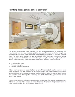
Advantages of Gamma Camera • The imaging time is only 1-2min. • It can distinguish 2 sources about 5mm apart.
Types of imaging in Nuclear Medicine • Planar (Gamma Camera). • Static. • Dynamic. • Total Body. • Tomographic (SPECT).
Static Imaging • It is the basic type of imaging. • The patient is injected before imaging. • The camera head is located at the organ of interest. • For dual head cameras two images can be acquired at the same time. • The stopping mechanism is either by Count or Time.
Static Imaging • The matrix size is defined according to the need from each exam starting from 64X64 up to 1024 X 1024. • The zoom is defined according to the size of the organ of interest. • Examples: • Thyroid imaging: 500 Kc acquisition count or 5 Min acquisition time with injected dose of 5 mCi matrix= 128 X128 Zoom = 2 : 1
Static Imaging • Bone imaging: 500 Kc acquisition count or 5 Min acquisition time for each position with injected dose of 20 mCi matrix= 512 X512 Zoom = 1 : 1
SPECT imaging • What is SPECT ? • Single photon to differentiate from two annihilation photons • Generation of cross - sectional images • Images from various angular projections
Collectively, the different projections contents represent the basic raw data, which is then mathematically reconstructed to yield the transverse section images
Dual head scanner • Single head SPECT