Download
1 / 30
300 likes | 448 Vues
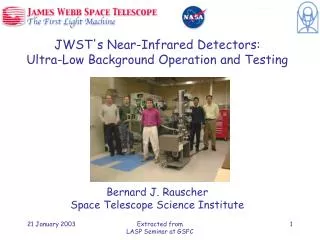
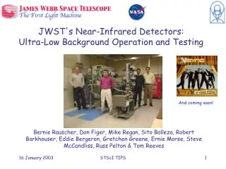
JWST's Near-Infrared Detectors: Ultra-Low Background Operation and Testing. Bernie Rauscher, Don Figer, Mike Regan, Sito Balleza, Robert Barkhouser, Eddie Bergeron, Gretchen Greene, Ernie Morse, Steve McCandliss, Russ Pelton & Tom Reeves. And coming soon!. Outline.

E N D
JWST's Near-Infrared Detectors:Ultra-Low Background Operation and Testing Bernie Rauscher, Don Figer, Mike Regan, Sito Balleza, Robert Barkhouser, Eddie Bergeron, Gretchen Greene, Ernie Morse, Steve McCandliss, Russ Pelton & Tom Reeves And coming soon! STScI TIPS
Outline • What is a Near-Infrared Array Detector? • JWST Science Drivers • Detector Requirements • Detector testing at STScI/JHU • Optimal Use • Summary STScI TIPS
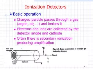
JWST’s IR Arrays are “Hybrid” Sensors • PN junctions are “bump bonded” to a silicon readout multiplexer (MUX). • Silicon technology is more advanced than other semiconductor electronics technology. • The “bump bonds” are made of indium. STScI TIPS
1.E+02 Sunshield 1.E+01 JWST requirement 1.E+00 Signal [e-/sec/pix] JWST goal 1.E-01 R=5 1.E-02 Zodiacal Light 1.E-03 R=1000 1.E-04 0.1 1 10 Wavelength [mm] JWST Needs Very Good Near Infrared Detectors! • Completing the JWST Design Reference Mission “on time” requires background limited near-infrared (NIR) broadband imaging • Zodiacal light is the dominant background component in the NIR • The total NIR detector noise requirement is therefore =10 e- rms in a t=1000 seconds exposure. • NIRSpec will probably be detector noise limited. The total noise goal is =3 e- rms per 1000 seconds exposure STScI TIPS
Detector Testing at STScI/JHU:Independent Detector Testing Laboratory STScI TIPS
Tom Reeves Lab Technician Robert Barkhouser Optical Engineer Eddie Bergeron Data Analyst Past and present personnel Bernie Rauscher Project Scientist Utkarsh Sharma Graduate Student Mike Telewicz Intern Steve McCandliss JHU Lead Ernie Morse Data Analyst Gretchen Greene Mechanical Engineer Scott Fels Intern Don Figer Director Monica Rivera Intern Sito Balleza Systems Engineer Mike Regan System Scientist Russ Pelton Technician STScI TIPS
Dark Current • Lowest measured dark current is ~0.006 e-/s/pixel. STScI TIPS
IDTL Measurements: Read Noise • Read noise is ~10 e- for Fowler-8. (system read noise is ~2.5 e-) STScI TIPS
IDTL Measurements: Conversion Gain Per correlateddouble sample STScI TIPS
Hawaii Shirt IDTL Test System Hawaii Detector STScI TIPS
Then & Now November 2000 November 2002 STScI TIPS
Raytheon ALADDIN Rockwell HAWAII-1R Jan. ‘01 (MUX) Feb. ‘02 (MUX) Apr. ‘02 (SCA) Raytheon SB-304 Rockwell HAWAII-2RG Nov. ‘02 (MUX) Jan. ‘03 (MUX) IDTL First Light Images Rockwell HAWAII-1RG Jun. ‘02 (MUX) Jul. ‘02 (SCA) STScI TIPS
IDTL Test System Leach II Controller Electronics Dewar Entrance Window Vacuum Hose He Lines STScI TIPS
Detector Readout System T=30-50 K Unix Instrument Control Computer Warm Harness COTS Leach II IR Array Controller T~293 K Cryogenic Harness JWST SCA Detector Customization Circuit STScI TIPS
Rockwell HAWAII-2RG Detector Customization Circuit (DCC) An Adaptable Readout System • The only hardware change required to run a different detector is swap-in a DCC. • We have DCCs for the following detectors. • Raytheon • SB-290 • SB-304 • Rockwell • HAWAII-1R • HAWAII-1RG • HAWAII-2RG • Each DCC is a multi-layer PCB. Extensive use of surface mount technology. Includes flexible “neck” to simplify interfacing. STScI TIPS
Raytheon SB-290/SB-304 Rockwell HAWAII-2RG Close-up ofDetector Customization Circuits (DCCs) STScI TIPS
Optimal Use • JWST Detector Readout Strategies • Use of Reference Pixels STScI TIPS
MULTIACCUM Detector Readout MULTIACCUM parameters: texpose = exposure time, t1 = frame time, and t2 = group time. The small overhead associated with finishing the last group of samples is not included in the exposure time. Detector Readout • JWST science requires MULTIACCUM and SUBARRAY readout. • Other readout “modes” can be implemented using parameters. • For example, Fowler-8 can be implemented as MULTIACCUM-2x8. • Cosmic rays may be rejected either on the ground or on-orbit. STScI TIPS
Raytheon 1024x1024 MIR MUX Raytheon 2Kx2K NIR Module Rockwell 2Kx2K NIR Module Reference Pixels • All candidate JWST detectors have reference pixels • Reference pixels are insensitive to light • In all other ways, designed to mimic a regular light-sensitive pixel • NIR detector testing at University of Rochester, University of Hawaii, and in the IDTL at STScI -> reference pixels work! • Reference pixel subtraction is a standard part of IDTL data reduction pipeline STScI TIPS
Use of Reference Pixels • We have begun to explore how reference pixels should be used. Approaches considered include the following. • Maximal averaging (average all reference pixels together and subtract the mean) • Spatial averaging • Temporal averaging • Spatial averaging is now a standard part of IDTL calibration pipeline STScI TIPS
A Picture of IDTL System Noise • Shorting resistor mounted at SCA location • 1/f “tail” causes horizontal banding. • Total noise is =7 e- rms per correlated double sample. STScI TIPS
After Before Averaging small numbersof reference pixels adds noise • Averaged the last 4 columns in each row and performed row-by-row subtraction STScI TIPS
This is a standardpart of the IDTL datacalibration pipeline Spatial Averaging • In spatial averaging, data from many (~64 rows) of reference pixels are used to calibrate each row in the image • A Savitzky-Golay smoothing filter is used to fit a smooth and continuous reference column • This reference column is subtracted from each column in the image • Using this technique, we can remove some 1/f noise power within individual frames • In practice, this technique works very well STScI TIPS
Spatial Averaging: Before & After Before After STScI TIPS
Rockwell HAWAII-1RG Double Correlated Sampling image. Read noise is ~15 e- rms (=5.3 e- using Fowler-8 sampling). Fit to reference columns using Savitzky-Golay filtering to smooth averaged reference pixel data in each row.. Spatial Averaging:Example using Rockwell HAWAII-1RG Detector STScI TIPS
Spatial Averaging Works! IDTL dark ramp. Astrisks include reference pixel correction using the Spatial Averaging method. Pluses do not. Fitted slope is =0.006 ± .001 e-/s/pixel. STScI TIPS
Temporal Averaging • Dwell on the reference pixel and sample many times before clocking next pixel • Potentially removes most 1/f • Not tried this in IDTL yet. U. Hawaii has reported some problems with reference pixels heating up STScI TIPS
Temporal Averaging: Before & After Before After STScI TIPS
Summary • The Independent Detector Testing Laboratory (IDTL) at STScI/JHU is up and running • Test results including dark current, read noise, conversion gain, and persistence are in good agreement with other JWST test labs • Reference pixels work and are an invaluable part of the data calibration pipeline • Spatial averaging works well and is robust STScI TIPS