Download
1 / 36
360 likes | 479 Vues
New Flow Actuation Concepts to be Studied Within European Technology Program ADVACT. AVT - 128 RTO-Meeting Prague, October 4 – 7, 2004 Dr. Sven-J. Hiller MTU Aero Engine Munich. Contents. Status and Motivation for the Link between Fluid Mechanics and Microsystems.

E N D
New Flow Actuation Concepts to be Studied Within European Technology Program ADVACT AVT - 128 RTO-Meeting Prague, October 4 – 7, 2004 Dr. Sven-J. Hiller MTU Aero Engine Munich
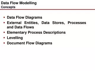
Contents Status and Motivation for the Link between Fluid Mechanics and Microsystems 6th Framework Program ADVACT Flow Actuation Concepts – Examples Numerical Simulation Issues and Examples Dr. Sven-J. Hiller (MTU Aero Engine)
Why becomes flow actuation so attractive now? • First experiments with flow actuation goes back in the 40’s of the last century Pulsed hot wire triggers instability waves • Growing interests in flow control due to wider knowledge about the flow physics • Achievement in e.g. efficiency growth on the traditional design way is limited by the amount of effort necessary (time and costs) and uncertainties (manufacturing) • Recent achievements in simulation technique, control science (growing computer capabilities, more efficient control algorithm, embedded systems) promise new ways for further efficiency growth and better operability, e.g. control loops with feedback Dr. Sven-J. Hiller (MTU Aero Engine)
Comparing Aero Engine Industry with Automotive Industry • Electronic Microsystems widely used in modern cars • Premium class cars equipped with ~ 3.5 km (2 miles) wiring • Minor usage of Microsystems in Aero Engines • Some of the reasons may be: • Lower number of pieces • Harsh environment • Reliability • less experiences with Microsystems • high level of optimal designs already achieved (i.e. efficiency, life cycles) Expecting a change in the Aero Engine Industry in mid-term time frame Dr. Sven-J. Hiller (MTU Aero Engine)
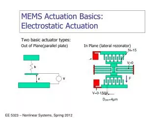
Two Major Braches in MEMS Application in Turbomachinery Flow Actuation by Microsystems Micro Turbomachines(Pumps, Gasturbines) Autarkic Energy Supplierdue to their high energy density(replacement of conventional batteries) Very Local Flow interaction Active Energy Conversion with the fluid enables the establishing of control loops Benefits: Size, Weight Benefits: Size, Weight, Control Loops Step on the way towards a clever, fully controlled engine Kang et al. (2003)(Stanford) Frechette et al. (2000) (MIT) Dr. Sven-J. Hiller (MTU Aero Engine)
Vision: Smart Compressor • Objectives: • Increase in Efficiency by better use of design space in aerodynamics • Surge Margin • Blade Vibration • Increase in efficiency by reduced clearances • Reduction in cost and weight by reduced number of parts Active Surge Control Active Clearance Control • Attempt: • Active Surge Control • Active Vibration Control • Active Clearance Control • Using Microsystems and smart materials Active Vibration Control Dr. Sven-J. Hiller (MTU Aero Engine)
Ambition for modern flow control concepts • Modern aero engines already achieved a high level of efficiency (based on huge experience basis) • Further significant increase is a question of benefit / requirements vs. effort • Regulation and Laws (environmental impact (noise, pollution), taxes) • Cost (development, manufacturing, maintenance) • Cost (operation, end-user) • But: all the statements base on a single “Working / Design / Warranty Point” consideration • Reality is a broad spectra of “Working Points”, ”Power Settings”, etc. • Many different “Off-Design” Conditions (e.g. short range air transportation) Dr. Sven-J. Hiller (MTU Aero Engine)
Consequences • The “Time Integral” is the amount of energy used to achieve a certain condition, location etc. • A better performance outside the “Design Point” has the potential to reduce the total amount of energy required • Improvement of the so-called “Off-Design Performance” (will also increase the Design Performance as well) promise an energy saving in general Focus on “Off-Design” Conditions under External Control Altitude Short Range vs. Long Range Mission Time Dr. Sven-J. Hiller (MTU Aero Engine)
Contents Status and Motivation for the Link between Fluid Mechanics and Microsystems 6th Framework Program ADVACT Flow Actuation Concepts – Examples Numerical Simulation Issues and Examples Dr. Sven-J. Hiller (MTU Aero Engine)
Attractiveness of Microsystems for Flow Actuation (locally) • Laws of the Fluid Mechanics are highly non-linear (sometimes chaotic) • Small change at one side can causes significant change on the other side • Urgent need to find the most efficient flow scenarios • Boundary Layer Flow (see also AVT-111) • Flow Separation and Reattachment • Transition (onset and delay) • Unstable Flow (Bifurcation) • Buoyancy-driven Flow Dr. Sven-J. Hiller (MTU Aero Engine)
Attractiveness of Microsystems for Complex Flow Scenarios • Sensitive Flow Scenarios • Shock location • Shock – Boundary Layer Interaction • Vortex-dominate Flow • Wing-Tip Vortex (Delta-Wing, etc.) • Noise and Acoustics • Aero acoustics • Instabilities (burner instabilities, etc.) • Bifurcation of the Complex Flow Scenarios • Flow at Adverse Pressure Gradient (Dynamic Stall, etc.) • Compressor Surge and Stall Dr. Sven-J. Hiller (MTU Aero Engine)
6th Framework Program ADVACT • EC launched within the 6th Framework the research project ADVACT “Development of ADVanced ACTuation Concepts to Provide a Step Change in Technology Used in Future Aero-Engine Control Systems” • Joint Research Program of Industrial Partners and Universities • Runs 48 month from July 2004 to June 2008 Dr. Sven-J. Hiller (MTU Aero Engine)
Main Objectives • “… generic study of the benefits of expanded actuation capabilities couples to development of specific technology which will show the capabilities for identified applications. “ • 9 Work Packages (see John Webster’s Presentation) • Focus on WP 2 “MEMS Development and Cascade Airflow Control” (Lead: MTU) • Close link to WP 3 “Boundary Layer Control in Intake and Ducts” (Lead: Snecma) • Partners in WP2: • MTU • Rolls-Royce • Snecma • Onera • IEMN (Institut d’Électronique de Microélectronique et de Nanotechnologie of CNRS) Dr. Sven-J. Hiller (MTU Aero Engine)
Compressor Stability Flow effects involved • Flow Separation at the blade surface during Off-Design (Airfoil Stall) • Induced Flow Separation through 3D Tip Clearance Flow • Boundary Layer-Shock interaction, especially in the tip gap region of the rotor blade • Unstable Flow Regime when throttled (Stall & Surge) • Instabilities inside the flow (rotating and non-rotating instabilities) • Vortex-dominate Flow (Secondary Vortex / Passage Vortex) • Corner Stall Dr. Sven-J. Hiller (MTU Aero Engine)
Origin: Turbomachinery Flow • Cascade Flow (non-rotating) • Gap between Blade and (non-moving) Casing • Cold Conditions (Temperature less than any critical temperature for a actuator device) • Size in the order of 0.1% …1% of a typical HPC Blade Chord (20 µm … 200 µm) • Lab-Scale Demo Test • Compressor Flow (rotating) • Off-Design Conditions • Compressor Stall & Surge • Tip Clearance Flow Simplified to • information about the flow mechanism involved (Lab-Scale) • information concerning reliability, certification, etc. • concepts for possible control loops • adequate numerical simulation techniques • development of MEMS technology for actuators Dr. Sven-J. Hiller (MTU Aero Engine)
DPG = -10% D = +2% Pressure Ratio Efficiency Surge Margin Mass Flow Rate Upsizing of a Compressor Working Line Larger Power DensityHigher Thrust-Weight-Ratio Upsizing of the Working Line toward the Efficiency Optimum Upsizing of the Working Line enables a significant improvement of the Power Density and Efficiency based on a modified Compressor Design Concept The compressor runs stabilised with a lower surge margin but higher efficiency Dr. Sven-J. Hiller (MTU Aero Engine)
Joint Research Project Between MTU, University of Armed Forces Munich and Engineering Office for Thermoacoustics (IfTA) • Objective were: • to identify some precursors of the LP compressor surge • to stabilize the LP compressor by air injection into the tip region of the Rotor 1 • Development of a controller device which detects the precursors and reacts on them (Active Surge Control) • Test vehicle: Larzac 04 Engine installed at the University Dr. Sven-J. Hiller (MTU Aero Engine)
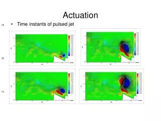
Opening of the Valve andStart of the Control Loop Aktuator Sensor Time Signals and Spectra @ Constant Throttle Position with ASC Sensor and Aktuator Signal 66% LPC Speed, 18% Valve Opening (Gear Factor = 30, 1st Search Range) Dr. Sven-J. Hiller (MTU Aero Engine)
Aktuator Sensor Time Signals and Spectra @ Continuous Throttling with ASC Sensor and Aktuator Signal 66% LPC Speed, 18% Valve Opening (Gear Factor = 40, 1st Search Range) Dr. Sven-J. Hiller (MTU Aero Engine)
Air Injection Nozzles in front of a Larzac Engine Injection Channels Turnable Nozzles External Air Supply Injection Casing (view from Rotor 1 forward) Dr. Sven-J. Hiller (MTU Aero Engine)
Air Injection • Comparable results from different research groups • all experiments base on discreet air injection equally spaced around the circumference • Typically ~12 air injectors at the circumference used Question: Can the Injection Mass Flow further reduced by a huge number of Micro Actuators? Dr. Sven-J. Hiller (MTU Aero Engine)
Contents Status and Motivation for the link between Fluid Mechanics and Microsystems 6th Framework Program ADVACT Flow Actuation Concepts – Examples Numerical Simulation Issues and Examples Dr. Sven-J. Hiller (MTU Aero Engine)
Compressor Rotor Blade near Stall Condition (simulated oil flow) Origin of Vortex Huge Secondary Vortex enhanced by the Tip Clearance Leakage High Incidence Corner Stall The Key: Tip Clearance Flow -> determine Efficiency and Stall Margin Dr. Sven-J. Hiller (MTU Aero Engine)
Adaptive Blade Shape • Control of Curvature means Control of Stall Onset (in certain limits) • 4 Options (mechanical) • Nose-Dropping Devices (DLR - Geissler/Trenker) • Actuated Flaps at Suction Side / Trailing Edge (ONERA, CEDRAT) (e.g. piezoactuators) • Shape Adaptive Airfoil (TU Kassel – Müller/Lawerenz, segmented airfoil) • Local Thickness Change by surface mounted devices • “Flexible” Blade Shape (fluidic, e.g. aspirated / transpired airfoil) in order to delay dynamic stall AVT-111 Chandrasekhara (NASA Ames) AVT-111 Glezer (Georgia Tec) Dr. Sven-J. Hiller (MTU Aero Engine)
MiniTED = Miniature Trailing Edge Devices • Very small high-lift devices attached at the trailing edge of an airfoil • Co-operation between DLR (Institute for Aerodynamics Braunschweig) and Airbus • Transsonic and high Reynolds Number Flow Rossow (DLR) • Method applicable as a Virtual Inlet Guide Vane (VIGV) in turbo machines • Typical HPC chord 1 in (~25 mm) -> Flap 1% -> 0.01 in (250 µm) Dr. Sven-J. Hiller (MTU Aero Engine)
Sub-layer vortex generators vortex system generated downstream enhances the energy transport from the outer flow into the near-wall regions and energises the boundary layer Bauer, EADS AVT-111 Liu (Texas) Dr. Sven-J. Hiller (MTU Aero Engine)
Aerodynamic Airfoil Shape Change Controlled Link between Pressure and Suction Side Synthetic Jets Array used for “virtual” airfoil shape change (aspirated / transpired airfoil) AVT-111 Glezer (Georgia Tec) Dr. Sven-J. Hiller (MTU Aero Engine)
What’s New within ADVACT? • many effects are known • some are well understood, other partially • mainly developed with the background of external (wing) or pure aerodynamics (flat plate) Our Objective • bring the effects into a turbo machine environment, e.g. internal aerodynamics • assessment of the various effects in an unsteady rotor-stator environment • assessment of the additional requirements concerning certification, reliability, aging, design and maintenance of an aero engine Dr. Sven-J. Hiller (MTU Aero Engine)
Contents Status and Motivation for the link between Fluid Mechanics and Microsystems 6th Framework Program ADVACT Flow Actuation Concepts – Examples Numerical Simulation Issues and Examples Dr. Sven-J. Hiller (MTU Aero Engine)
Simulation Techniques Issues • Domains simulated embodies very different length scales • because of smooth mesh coarsening from the actuator to the airfoil the mesh sizes tend to be very large • Some Questions to be answered: • Continuums Mechanics still valid? • Role of Turbulence Models (URANS) and Wall Treatments • What’s about DNS / LES / DES? • Simplification thinkable? Dr. Sven-J. Hiller (MTU Aero Engine)
Simulation Techniques – Continuums Mechanics still valid? • Stationary statistics (large number of molecules) and continuity of transport quantities (viscosity and diffusivity) must be valid • Assumption: For Air: Lgas = 1 µm (10-6 m) For simulation domains with edges larger then 1 µm the application of Navier-Stokes-based solvers (e.g. standard (U)RANS CFD solvers) are still valid ! Dr. Sven-J. Hiller (MTU Aero Engine)
Characteristic Values Ratio of mean free path to length scale of the flowNavier-Stokes with slip or non-slip conditions at the wall Knudsen Number Ratio of mean molecular spacing to diameter of typical gas molecules>> 1 diluted gas Ratio of velocity to speed of soundsub- / trans- / supersonic flow Mach Number Ratio of initial forces to viscous forceslaminar / transient / turbulent Reynolds Number Dr. Sven-J. Hiller (MTU Aero Engine)
NASA Test Cases (2003) • NASA Langley initiated and published 3 test cases for flow actuators and flow actuation for CFD validation • Case 1: Synthetic Jet into Quiescent Air • Case 2: Synthetic Jet in a Crossflow • Case 3: Flow over a Hump Model (Actuator Control) Wall-mounted Glauert-Goldschmied type body Slot across span Dr. Sven-J. Hiller (MTU Aero Engine)
CFD Validation for Case 3 (Förster, Hiller) • Usage of in-house and commercial solver (in the frame of a diploma thesis) • Aim: meet the measured re-attachment point of the separated hump flow • Assessment of the effects of a Synthetic Jet onto the main flow Mainf=0.1 Re ~ 106 measured Synthetic Jet Detail k-e SST RNG k-w BSL SSG Jet Slot Width ~ 0.5% Chord Length Reattachment Point Dr. Sven-J. Hiller (MTU Aero Engine)
Simplification (proposed by Orkwis (Connecticut)) • The effect of a Synthetic Jet onto the main flow will be simulated as a special kind of momentum sources rather then the detailed flow interaction between the jet and the main flow • Pro: still working on the “coarser” main flow mesh with short turn-around times • Cons: a huge calibration task is necessary in advance (database-like) Details accurately reproduced Orkwis Steady w/ LDSTs Time-averaged and Steady-State+LDST Solutions: 90˚ SJ Time-average Dr. Sven-J. Hiller (MTU Aero Engine)
Thank You For Your Attention Questions? Dr. Sven-J. Hiller (MTU Aero Engine)