MaPMT Readout Workshop / Introduction
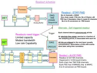
MaPMT Readout Workshop / Introduction. MaPMT Workshop Imperial College 26/27 June 2003. Franz Muheim University of Edinburgh. Workshop Agenda & Goals. Outline of MaPMT project Reports/Presentations MaPMT/Beetle studies Photo detector integration issues Possible Readout schemes

MaPMT Readout Workshop / Introduction
E N D
Presentation Transcript
MaPMT Readout Workshop / Introduction MaPMT Workshop Imperial College 26/27 June 2003 Franz Muheim University of Edinburgh
Workshop Agenda & Goals • Outline of MaPMT project • Reports/Presentations • MaPMT/Beetle studies • Photo detector integration issues • Possible Readout schemes • Level-1 Electronics, PINT results • Plans for this summer • Define MaPMT read-out project • Produce list of tasks necessary to get job done • Identify conflicting requirements • Prioritise different options (if possible) • Planning of schedules and milestones • MaPMT plans and schedule • Hope for lots of fruitful discussions F. Muheim
MaPMTs for LHCb RICH • Multianode Photo Multiplier Tubes • Single photo tubecontaining 8x8 array of 64 dynode chains 2.1 mm pixel size, 0.2 mm gap • Bialkali photo cathode, UV glass window QE = 22 % at = 380 nm • Lenses • with one flat and one curvedsurface • Increases active area fraction to 85% • effective pixel size 3.0 mm • Readout Electronics • ASIC preamplifier chip with pipeline • Readout architecture L0 & L1 • Mechanics • Photo detector mounts & motherboard • Magnetic field shielding, mu-metal F. Muheim
MaPMT/Beetle Project • MaPMT R7600-03-M64 with 8 dynode stages • gain: 50000 HV 800 V • Front-End electronics • Beetle1.2chip • single photon equivalent 60 mV (2 mip) • signal / noise ratio 40 • analogue or binary readout mode • MaPMT R7600-03-M64 with 12 dynode stages • gain: 300’000 HV 800 V • Beetle1.2-MaPMTchip with gain adaption • single photon equivalent 30 mV (2 mip) • signal / noise ratio 40 • analogue or binary readout mode F. Muheim
MaPMT Plans & Schedule • Read out the8 dynode stage MaPMT • with Beetle1.2 in analogue and binary mode • using the Heidelberg board restricted to 12 channelsJan - June 03 • Read out the12 dynode stage MaPMT • with Beetle1.2MA0 in analogue and binary mode • using the Heidelberg board, restricted to 12 channelsApril - June 03 • Read out all 64 channelsof one or more MaPMTs • with the Beetle1.2/Beetle-MA0 in analogue and binary mode • with Beetle PCBoard July 03 - • Testbeam • Prepare and operate a cluster of MaPMTs in a testbeam, read out with the Beetle1.2 or Beetle-MA0chipMay - Sep 03 F. Muheim
Electronic Cost Comparison • Main Inputs • 232 modules with 16 MaPMTs, 8 Beetle chips, 1024 channels • 220 SFr/optical link, 190 SFr/ 4 copper links 5kSFr/ L1 board • Binary Electronics • 232 optical links, 30 L1 boards1250 kSFr • Analogue Electronics • 4x1856 copper links, 116 L1 boards2100 kSFr • TDR cost for comparison 1600 kSFr • difference to binary850 kSFr • Digital Electronics • 1856 optical links, 78 L1 boards1970 kSFr • difference to binary 720 kSFr • Cost differences are understood • data links costs are rather robust O(50 kSFr) • optimisation for L1 board necessary O(100 kSFr) • absolute cost of L0 electronics needs to be reassessed F. Muheim
Major Issues • MaPMT/Beetle studies • BoardBeetle July 03 • Testbeam 13 Aug - 9 Sep • MaPMT type decision • 8 vs 12 dynode stages Sep 03 • Binary vs analogue/digital readout • cost versus risks (common mode, comparator) • only decision possible now is analogue or digital • proposal - analogue or digital as baselineJune 03 • Design of L0 motherboard • includes cooling, on critical path Jan 04 • report from meeting at CERN 22.5.03 • Software • Performance studies, robustness Sep 03 F. Muheim
Overall Schedule • 1 year old, • produced for June 2002 review, need to update • July 2002 Resume design of Beetle chip done • Oct 2002 Resume Motherboard design starting now • 1 Mar 2003 Choose MaPMTs • Mar 2003 Start tendering not started • 1 Oct 2003 Place MaPMT Order • Jan 2004 L0 F/E Electronics and Motherboard (MB) design completed • Mar 2004 Start Photodetector testing • July 2004 10% of MaPMTs delivered • Jan 2005 L0 - F/E Electronics and MB R&D completed • Mar 2006 100% of MaPMTs delivered and tested • Mar 2006 100% production and testing of L0 and L1 units • June 2006 100% of photodetector modules assembled F. Muheim
Status of MaPMT Project • Large efforthas started for MaPMT projectin 2003 • Measurements of 8-dynode stage MaPMTs signal shape with Beetle1.2 has highest priority • Measurements with Beetle1.2MA0 are promising • More effort is needed • Need to catch up delays, 7 monthsfor L0 Motherboard • MaPMT is baseline • More effortavailable • Need to re-think organisation of MaPMT projectnow • Many importantdecisions need to be taken soon F. Muheim
Backup Slides F. Muheim
Multianode Photo Multiplier • Single photo tubecontaining 8x8 array of 64 dynode chains 2.1 mm pixel size, 0.2 mm gap • Gain: 3.105 at 800 V • Bialkali photo cathode, QE = 22 % at = 380 nm • UV glass window, was borosilicate, QE dE increased by 50 % MaPMT QE [%] Wavelength [nm] F. Muheim
no lens lens 0 mrad lens lens 400 mrad Quartz Lenses • MAPMT active area fraction: 38% (includes pixel gap) • Increase with quartz lens with one flat and one curved surface to 85% • effective pixel size 3.0 mm Demagnification (f -d)/f 2/3 F. Muheim
3x3 MaPMT Cluster Test • Measurements with • MaPMT: HV = -1000V • Data • subtract cross-talk and common-mode • Fit # of photo electrons per event: Single channel spectrum • Cherenkov ring, 6000 events • Observe in data backgroundnpe= 6.96 0.33 0.26 p.e. • Expect from simulationnpe= 6.49 0.17 F. Muheim
Electronics Costs • Major cost differences in • data links • L1 boards • L0 Electronics • 232 modules • 16 MaPMTs, 1024 channels, 8 Beetle chips • 4 data links per beetle, 128: 4 multiplexing, 40 MHz clock • cost very similar for all options • Binary Electronics • optical links to L1 board • 32 : 1 multiplexing (1bit per data link) • 232 optical links, 1 per module (was 2) • costs from John Bibby • cost per optical link220 SFr, total 50 kSFr • 30 L1 boards, 5 kSFr/board, total 150 kSFr • L1 costs reduced by 300 kSFr wrt to TDR F. Muheim
Analogue/Digital Electronics • Analogue Electronics • similar to VELO, with copper links over 60 m • link costs include driver, differential link receiver and ADC (costs from Thomas Ruf) • 4 x 1856 links, 190 SFr / 4 links, total data links350 kSFr • L1 board input: 64 links = 16 cables • 116 L1 boards, 5 kSFr/board, total L1 boards 580 kSFr • Analogue/Digital Electronics • similar to Inner Tracker, ADC at outer detector rim • need rad tolerant ADC (15kRad), • costs from Achim Vollhardt • 4:1 multiplexing with 8bit ADC • 1856 optical links, 252 SFr/link, total data links 470 kSFr • L1 board, input 96 optical links = 6 ribbons • 78 L1 boards, 5 kSFr/board, total L1 boards 390 kSFr F. Muheim
Comparator Review • Phone Meeting of Beetle Users • 30 April 03 • comparing of notes • digital switching noise, 80 MHz, on analogue lines • Comparator Discussion • closed loop of understanding • small differences resolved • conclusions remain the same • 3bits are marginal, • 5bits has comfortable margin • Comparator in Beetle1.2 • 3 bits, no access to negative offsets • Comparator in Beetle1.3 • 5 bits, different sign for Offset and Delta IDAC • will be submitted in June F. Muheim
Allocation of Personnel • Agreed at RICH group leader’s meeting CERN, 26 Feb 03 • Immediatepersonnelrequirements • Setup of read-out and testing A) and B) Edinburgh • Testing of BeetleMA0 B) Oxford • Production of PCBoard for C) Imperial College • Consulting for A) B) SW,JB,NS,DP • Procurement strategy ok • Design of L0 motherboardCambridge, Oxford Genova • CoordinationFM • Additional personnel required in May • Cooling strategy Genova • Higher channel occupancyCERN, Edinburgh • Bleeder board for test beam Cambridge • jigsUK/CERN • moulded lensesGenova F. Muheim
To Do List (on 28 April) • Read-out of 8-dynode MaPMT with Beetle1.2 • (re-)connect MaPMT done • measure analogue spectra with LED done • take data in binary mode July • Review of electronics cost • binary vs analogue vs digital read-out done • Comparator review done • Decision on binary vs analogue • cost versus risks (common mode) ??? • Read-out of 12-dynode MaPMT with Beetle1.2 • testing of Beetle1.2MA0 done • measure with LED analogue spectradone • take data in binary mode July F. Muheim