Download
1 / 11
110 likes | 253 Vues
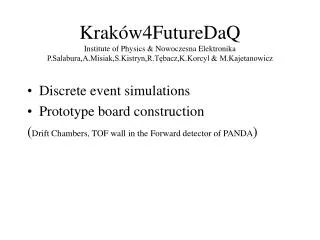
Kraków4FutureDaQ Institute of Physics & Nowoczesna Elektronika P.Salabura,A.Misiak,S.Kistryn,R.Tębacz,K.Korcyl & M.Kajetanowicz. D i screte event simulations Prototype board construction ( Drift Chambers, TOF wall in the Forward detector of PANDA ).

E N D
Kraków4FutureDaQInstitute of Physics & Nowoczesna ElektronikaP.Salabura,A.Misiak,S.Kistryn,R.Tębacz,K.Korcyl & M.Kajetanowicz • Discrete event simulations • Prototype board construction (Drift Chambers, TOF wall in the Forward detector of PANDA)
Modeling DAQ(Krzysztof Korcyl & Radosław Trębacz) • The PTOLEMY environment: • http://ptolemy.berkeley.edu (classic version) • DE (Discrete Event) domain • simulation program maintains time-ordered list of moments when the modelled system (or part of it) is allowed to change • C++ to build models of components; • Tcl-like scripts to connect components and form architectures; • ROOT to process proprietary ascii files with results • Easy and quick to start: unified and simple interface between components • Substantial expertise (K.Korcyl): modeling TDAQ system (Linux PCs + large GE network) for the LHC experiment ATLAS. • Other environments: SystemC, (?) – need evaluation of overheads
Modeling DAQ - II • Modeling steps: • Questions: specify questions/issues of interests („how does it work?” – does not work; rather: what is max throughput, how long queues, etc) • Parameterization: simplify components as much as possible but with sufficient details to reproduce behavioral aspects relevant to the issues studied. Each model has a list of measurable parameters. • Calibration: collect values for the model parameters • for the software processes: instrument software with time stamps and run dedicated test measurements. • for the hardware components: use oscilloscopes, logic analysers in dedicated setups. • Validation: model test setups using parameterized models – cross-check with measurements – refine parameterization or/and calibrationif necessary • Prediction: predict performance for the full size system with nominal rates: evaluate various architectures and impact of the possible policies on the overall system performance
Node N-1 Node N Node 1 Node 2 Sink Source Ring Architecture
FIFO FIFO Processing Node Compute Engine Busy Intelligent Switch GBitEth Out GBitEth In
Operation • Data is transported between nodes via UDP (no check for packet loss or transmission error) • If the local compute resource is idle, the raw input data is converted into processed data, and send to resource for processing • If the local compute resource is busy, the data packet is forwarded to the next node in the chain • Forwarding of processed data from the compute engine has priority over transporting raw data • The switch can transport in parallel • Raw data from the input to the compute source • Processed data to the output • At some point, packets will be lost because: • they were forwarded to the sink without being processed • of the network limited throughput • Question: • What is the rate of packet loss as a function of the parameters of the system • What is the FIFO occupation in each of the processing nodes
Initial Set of Parameters • Raw data packet size (<1500 bytes) • Processed data packet size (<1500 bytes) • FIFO size (<64 KBytes) • Compute time (> 1 ms) • Load (generated by the source: < 100% GE) • Number of nodes
TDC for Future DAQ? • Multichannel (32), multihit devices (internal memories): HPTDC (CERN), TDC-F1 acam, .. • Variable resolution i.e HPTDC: 785ps, 195ps, 98ps, 25ps (LSB) - measurement wrt. free running clock, self calibration • Filtering of hits according to trigger matching mechanism: Trigger latencies up to 50 s, overlaping trigger handling time • Input hit rates up to few MHz/channel • High output data rates: 40-50 MHz clock, 8-32 bits parralel output • Does it fit our requirements?
Many different timing detectors : i.e PANDA: Scintilators, Drift chambers, CBM: RPC’s : 1 : 0.03ns resolution needed • Forward Detector @PANDA (Drift chambers to be build in UJ Kraków): • Hit rates up to 0.3 MHz, 1ns resolution, 200-300 ns time range, 6k wires • trigger rates? PANDA: many different trigger types, trigger latancies?, reaction rates of up to 107 reactions Intermediate step (?): TOF system for HADES RPC(M.Kajetanowicz) 4 TDC/board: time, Time Over Threshold Fast Ethernet interface: ETRAX 100 Mbit/s Switch 1Gigabit Ethernet Node
Data driven TDC architecture 8 x Trigger FIFO (16) 4 channels grouped