Download
1 / 9
90 likes | 227 Vues
This document outlines the intricate design and operational strategies for the control, calibration, and gating of TPC pulsers. It covers essential functionalities such as charge injection into PASAs, real-time monitoring of critical voltages, and the configuration of various calibration parameters. The setup comprises dual crates accommodating ground-free configurations, allowing for improved performance and safety during operation. The integration of advanced communication interfaces, including Profibus and CAN-bus, facilitates efficient data management and control, targeting optimal performance in experimental environments.

E N D
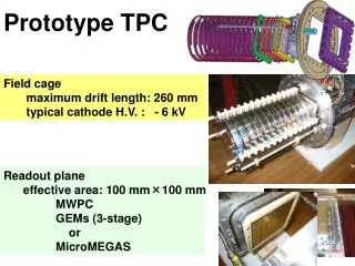
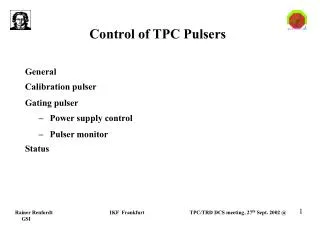
Control of TPC Pulsers General Calibration pulser Gating pulser • Power supply control • Pulser monitor Status
General Gate pulser: open/close gating grid - absorbs electrons from drift region - absorbs ions from amplification region Calib. Pulser: injects charge into PASAs - electronics test - electronics gain calibration Pulsers not accessible Goal: - all vital functions monitored - critical voltages remotely controlled Gate pulser Calib. pulser
Calibration pulser: schematics In control room In pit (on both sides of the TPC) (40 m distance)
Calibration pulser (2) 2 crates 6U ground free setup: everything (or at least the output stage) floating one point foreseen for possible ground connection 1 backplane distr. of power distr. of analog reference signal distr. of control signals for switching of channels (6 lines ?) 1 power supply:+-5V, +-12V status indication by LEDs 1 control board CAN-bus or Profibus interface FPGA DAC readout of supply voltages via ADC inputs (clock, trigger) galvanically isolated which cables, which standard (LVDS, NIM ...) not clear yet 5 (7) driver boards BNC connectors, ground free 8 driver channels per board Uout max: 3V (?) at 50 Ohm channels switchable low noise status indication by LEDs
For TPC partition: - normal pulsing incl. parameter variation: - on/off - selection of readout chamber(s) - Amplitude - single/multiple pulses - calibration procedure: fixed sequence of amplitudes & recording (DAQ & tape) Calibration pulser: control ECS DCS - on/off - selection of readout chamber(s) - Amplitude - single/multiple pulses PC - Load new pulseshape 120 m profibus Pulser
-130 V +100 V -100 V 5V 9 V Gating pulser (NA49) Gate out 10x Pulser Pulser Pulser Trigger in
+100 V -100 V -130 V -130 V Controller Controller Gating pulser (Alice) Profibus Gate out Gating monitor voltage moitor 5V, 9 V Trigger in Pulser Pulser Pulser To next crate RS 232 RS 232
Gating pulser: control ECS For TPC partition: - normal gating on/off - monitor gating - monitor voltages DCS - monitor gating - set/monitor voltages Trigger Gating on/off Profibus RS232 Gating pulser
Status Calib. Pulser: - prototype exists: NIM module, FPGA, DAC - details about Profibus connection not defined yet (manufacturer, model) Gating pulser: - design for pulser itself exists (Danilo, Zagreb) - study started how to pick up gating signal and control switching (IKF) - survey for remotely controllable power supplies started (IKF) (Agilent has system with 8 modules, 200V, but: IEEE 488 control!)