Digital Logic Design and Application ( 数字逻辑设计及应用 )
Digital Logic Design and Application ( 数字逻辑设计及应用 ). Review of Chapter 2 ( 第二章内容回顾 ). General Positional-Number-System Conversion ( 常用按位计数制的转换 ) Addition and Subtraction of Non-decimal Numbers ( 非十进制的加法和减法 ). Digital Logic Design and Application ( 数字逻辑设计及应用 ).


Digital Logic Design and Application ( 数字逻辑设计及应用 )
E N D
Presentation Transcript
Digital Logic Design and Application (数字逻辑设计及应用) Review of Chapter 2 (第二章内容回顾) • General Positional-Number-System Conversion • (常用按位计数制的转换) • Addition and Subtraction of Non-decimal Numbers • (非十进制的加法和减法)
Digital Logic Design and Application (数字逻辑设计及应用) Review of Chapter 2 (第二章内容回顾) • Representation of Negative Numbers (负数的表示) • Signed-Magnitude [ 符号-数值(原码)] • Complement Number Systems (补码数制) Radix – Complement (基数补码) Diminished Radix – Complement [ 基数减1补码(基数反码)]
Digital Logic Design and Application (数字逻辑设计及应用) Review of Chapter 2 (第二章内容回顾) • Binary Signed-Magnitude, Ones’– Complement, and Two’s – Complement Representation (二进制的原码、反码、补码表示) 直接由补码(反码)求二进制数值的大小:最高位位权为 -2n-1 (-2n-1 -1) (1011)2补=( )10
Digital Logic Design and Application (数字逻辑设计及应用) Review of Chapter 2 (第二章内容回顾) • Two’s – Complement Addition and Subtraction (二进制补码的加法和减法) • Overflow(溢出) • 如果加法运算产生的和超出了数制表示的范围,则结果发生了溢出(Overflow)。 • 如何判断溢出? • MSB C in与 C out 不同
Digital Logic Design and Application (数字逻辑设计及应用) Review of Chapter 2 (第二章内容回顾) • How to represent a 1-bit Decimal number with a 4-bit Binary code (如何用 4位二进制码 表示 1位十进制码)? • —— Binary Coded Decimal (BCD码) • (0.301)10=( )8421BCD
Digital Logic Design and Application (数字逻辑设计及应用) Review of Chapter 2 (第二章内容回顾) • Addition of BCD Digits (BCD数的加法) • 思考: • 两个BCD码 • 与两个4位二进制数 • 相加的区别?
Digital Logic Design and Application (数字逻辑设计及应用)
Digital Logic Design and Application (数字逻辑设计及应用) Review of Chapter 2 (第二章内容回顾) • Addition of BCD Digits (BCD数的加法) • 思考: • 何时需要进行修正? 如果(X+Y)产生进位信号C 或 在 1010~1111 之间 • 如何修正? • —— 结果加6
Digital Logic Design and Application (数字逻辑设计及应用) Review of Chapter 2 (第二章内容回顾) • Gray code(格雷码) • 任意相邻码字间只有一位数位变化 • 最高位的0和1只改变一次 • 最大数回到0也只有一位码元不同
Digital Logic Design and Application (数字逻辑设计及应用) 2.11 Gray code(格雷码) • 构造方法 • Reflected Code(反射码) • 直接构造 • The bits of an n-bit binary cord word are numbered from right to left, from 0 to n-1. [对 n位二进制的码字从右到左编号(0 ~ n-1)] • Bit i of a Gray-code code word is 0 if bits i and i+1 of the corresponding binary code word are the same, else bit i is 1. (若二进制码字的第 i 位和第 i + 1 位相同,则对应的葛莱码码字的第 i位为0,否则为1。)
Digital Logic Design and Application (数字逻辑设计及应用) Review of Chapter 2 (第二章内容回顾) From binary number to Gray code The width is same, the MSB is same; From left to right, if a bit in binary number is same as its left bit, the gray code is 0, if it is different, the gray code is 1. Examples: binary number: 1001 0010 0110 0011 Gray code: 1101 1011 0101 0010
Digital Logic Design and Application (数字逻辑设计及应用) Review of Chapter 2 (第二章内容回顾) • 构造方法 • 异或(XOR)运算:相异为1,相同为0 • Gn = Bn Bn = Gn • Gn-1 = Bn ⊕ Bn-1 Bn-1 = Gn ⊕ Gn-1 • …… • G0 = B1 ⊕ B0 B0 = Gn⊕Gn-1⊕… ⊕ G0
Digital Logic Design and Application (数字逻辑设计及应用) Chapter 3 Digital Circuits (数字电路) Give a knowledge of the Electrical aspects of Digital Circuits (介绍数字电路中的电气知识)
Digital Logic Design and Application (数字逻辑设计及应用) Consider some Questions(思考几个问题) • 在模拟的世界中如何表征数字系统? • 如何将物理上的实际值 映射为逻辑上的 0 和 1 ? • 什么时候考虑器件的逻辑功能; 什么时候考虑器件的模拟特性?
0 Vcc 1 R 0 1 VOUT Positive (正逻辑) Negative (负逻辑) VIN 获得高、低电平的基本原理 Digital Logic Design and Application (数字逻辑设计及应用) 3.1 Logic Signals and Gates(逻辑信号和门电路) • How to get the HIGH and LOW Voltage (如何获得高、低电平)? • HIGH to 0 or 1 (高电平对应 0 还是 1)?
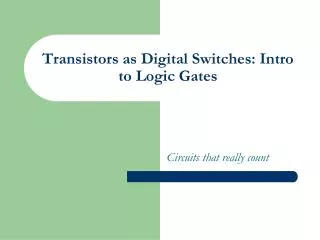
Switches Electronic switches are the basis of binary digital circuits A switch has three parts Source input, and output Current tries to flow from source input to output Control input Voltage controls whether that current can flow control input “off” source output input control input “on” source output input 16
Switches The amazing(令人惊奇的) shrinking(逐渐减小的) switch 1930s: Relays 1940s: Vacuum tubes 1950s: Discrete transistor 1960s: Integrated circuits (ICs) Initially just a few transistors on IC Then tens, hundreds, thousands... relay discrete transistor vacuum tube IC quarter (to see the relative size) 17
The CMOS Transistor CMOS transistor Basic switch in modern ICs 2.3 ...attracts electrons here, turning the channel between the source and drain into a conductor A positive voltage here... gate IC package oxide source drain IC (a) Silicon -- not quite a conductor or insulator: Semiconductor 18
The CMOS Transistor CMOS transistor Basic switch in modern ICs nMOS 1 0 gate does not conduct conducts pMOS 1 0 gate does not conduct conducts 2.3 19
Moore’s Law IC capacity(容量,集成度) doubling about every 18 months for several decades Known as “Moore’s Law” after Gordon Moore, co-founder of Intel Predicted(预言) in 1965 predicted that components per IC would double roughly(粗略地,大致上) every year or so 20
Moore’s Law For a particular(特定的) number of transistors, the IC area shrinks by half every 18 months Consider how much shrinking occurs in just 10 years (try drawing it) Enables incredibly(不能相信的,难以置信的) powerful computation in incredibly tiny devices
Moore’s Law Today’s ICs hold billions of transistors The first Pentium processor (early 1990s) needed only 3 million An Intel Pentium processor IC having millions of transistors
Digital Logic Design and Application (数字逻辑设计及应用) 3.1 Logic Signals and Gates(逻辑信号和门电路) • 从物理的角度 • 考虑电路如何工作,工作中的电气特性 • 实际物理器件不可避免的时间延迟问题 • 从逻辑角度 • 输入、输出的逻辑关系 三种基本逻辑:与、或、非
Boolean Logic GatesBuilding Blocks for Digital Circuits (Because Switches are Hard to Work With) “Logic gates” are better digital circuit building blocks than switches (transistors) Why?... 2.4 Abstraction(提取) reduces complexity! 24
Boolean Algebra and its Relation to Digital Circuits To understand the benefits of “logic gates” vs. switches, we should first understand Boolean algebra “Traditional” algebra Variables represent real numbers (x, y) Operators(运算器) operate on variables, return real numbers (2.5*x + y - 3) a 25
Boolean Algebra and its Relation to Digital Circuits Boolean Algebra Variables represent 0 or 1 only Operators return 0 or 1 only Basic operators AND: a AND b returns 1 only when both a=1 and b=1 OR: a OR b returns 1 if either (or both) a=1 or b=1 NOT: NOT a returns the opposite of a (1 if a=0, 0 if a=1) a 26
A B Z A A (逻辑符号) & A B Z Z B B Z Digital Logic Design and Application (数字逻辑设计及应用) 1、Basic Logic Function: AND(基本逻辑运算:与) Switch:1-on,0-off (开关:1通,0断) Lamp: 1-Light,0-out (灯:1亮,0不亮) Logic Circuit Truth Table (真值表) Produce a 1 output if and only if its inputs are all 1 (当且仅当所有输入全为1时,输出为1) 0 0 0 0 1 0 1 0 0 1 1 1 Logic Expression (逻辑表达式) Z = A · B
A A 真值表 逻辑符号 ≥1 A Z Z B B A B Z B Z Digital Logic Design and Application (数字逻辑设计及应用) 2、Basic Logic Function: OR(基本逻辑运算:或) Truth Table Logic Circuit 0 0 0 0 1 1 1 0 1 1 1 1 Produce a 1 output if any input is 1 (只要有任何一个输入为1,输出就为1) Logic Expression (逻辑表达式): Z = A + B
真值表 Logic Expression (逻辑表达式):Y = A = A’ (逻辑符号) 1 A Z Z R A Z A A Z 0 1 1 0 Digital Logic Design and Application (数字逻辑设计及应用) 3、Basic Logic Function: NOT(基本逻辑运算:非) Logic Circuit Truth Table Produce an output value that is the opposite of its input value. (产生一个与输入相反的输出) Usually called an Inverter(通常称为反相器)
NAND (与非) Logic Expression(逻辑表达式): Z = ( A · B ) ’ Logic Circuit ( 逻辑符号): & ≥1 Digital Logic Design and Application (数字逻辑设计及应用) 4、NAND and NOR Gates (与非 和 或非) • NOR (或非) • Logic Expression (逻辑表达式): Z = ( A + B ) ’ • Logic Circuit (逻辑符号):
& ≥1 Digital Logic Design and Application (数字逻辑设计及应用) Logical Operation (逻辑运算) NAND (与非) NOR (或非) Logic Circuit (逻辑符号) Logic Expression (逻辑表达式) Y=(A B) ’ ‘ Y=(A+B) ’ ‘ ž A B Y Y 0 0 1 1 Truth Table (真值表) 0 1 0 1 1 0 1 0 1 1 0 0
Boolean Algebra and its Relation to Digital Circuits Developed mid-1800’s by George Boole to formalize(使成正式)human thought Ex: “I’ll go to lunch if Mary goes OR John goes, AND Sally does not go.” Let F represent my going to lunch (1 means I go, 0 I don’t go) Likewise(类似地), m for Mary going, j for John, and s for Sally Then F = (m OR j) AND NOT(s) 32
Converting to Boolean Equations Q1. A fire sprinkler(洒水器) system should spray(喷) water if high heat is sensed and the system is set to enabled. Answer: Let Boolean variable h represent “high heat is sensed,” e represent “enabled,” and F represent “spraying water.” Then an equation is: F = h AND e. a 33
Converting to Boolean Equations Q2. A car alarm should sound if the alarm is enabled, and either the car is shaken or the door is opened. Answer: Let a represent “alarm is enabled,” s represent “car is shaken,” d represent “door is opened,” and F represent “alarm sounds.” Then an equation is: F = a AND (s OR d). a 34
Relating Boolean Algebra to Digital Design Boolean algebra Boole’s intent: formalize human thought (mid-1800s) Switches For telephone switching and other electronic uses (1930s) Showed application of Boolean algebra to design of switch- based circuits Shannon (1938) Digital design
Digital Logic Design and Application (数字逻辑设计及应用) 3.2 Logic Families(逻辑系列) • 同一系列的芯片具有类似的输入、输出及内部电路特征,但逻辑功能不同。 • 不同系列的芯片可能不匹配 • CMOS系列 • TTL逻辑系列
5.0V 3.5V 1.5V 0.0V Digital Logic Design and Application (数字逻辑设计及应用) 3.3 CMOS Logic (CMOS逻辑) • CMOS Logic levels (COMS 逻辑电平) Logic 1 (High) [逻辑1(高态)] Logic 0 (Low) [逻辑0(低态)] A Typical Logic Circuit: 5-Volt Power Supply (典型的5V电源电压) Other Power-Supply Voltages: 3.3 ,2.5 or 1.8Volts (其它电源电压:3.3V ,2.5V或1.8V)
Drain (漏极) Source (源极) Vgs Gate (栅极 ) + Gate (栅极) + Vgs Source (源极) Drain (漏极) P-Channel (P沟道) Digital Logic Design and Application (数字逻辑设计及应用) 2、MOS Transistors (MOS晶体管) • Two Types: N-Channel and P-Channel (分为:N沟道 和 P沟道) N-Channel (N沟道)
Source (源极) Vgs + Gate (栅极) Drain (漏极) P-Channel (P沟道) Digital Logic Design and Application (数字逻辑设计及应用) 2、MOS Transistors (MOS晶体管) • Two Types: N-Channel and P-Channel (分为:N沟道 和 P沟道) • Usually (通常): • Vgs < = 0 • Vgs = 0 • Rds Very High • Off (截止状态) • Vgs Rds • On (导通状态)
Digital Logic Design and Application (数字逻辑设计及应用) 2、MOS Transistors (MOS晶体管) • The Gate of a MOS transistor has a very high impedance(阻抗). [ Over megohm (106 ohms)] [ MOS晶体管栅极阻抗非常高(>兆欧)] • Regardless of gate voltage (无论栅电压如何) Almost no current flows from the gate to source, or from the gate to drain. ( 栅-源、栅-漏之间几乎没有电流) ( Leakage(漏出) Current, Less than microampere (漏电流, A, 10-6A ) • The Gate is Capacitively(容性地) coupled to the source and drain( 栅极与源和漏极之间有容性耦合) The power need to charge and discharge this capacitance(电容) on each input signal transition accounts for a nontrivial(非平凡的) portion of a circuit’s power consumption (信号转换时,电容充放电,功耗较大).
+ VDD RD D + G iD vO + vI S – – Digital Logic Design and Application (数字逻辑设计及应用) MOS管的基本开关电路 只要电路参数选择合理 输入低,截止,输出高 输入高,导通,输出低
VDD = +5.0V Tp VOUT VIN Tn Digital Logic Design and Application (数字逻辑设计及应用) 3、Basic CMOS Inverter Circuit( 基本的CMOS反相器) • Functional Behavior (工作原理) • 1、VIN = 0.0V • VGSN = 0.0V, Tn Off (截止) • VGSP = VIN –VDD = –5.0V, Tp On (导通) • VOUT VDD = 5.0V
VDD = +5.0V Tp VOUT VIN Tn Digital Logic Design and Application (数字逻辑设计及应用) 3、Basic CMOS Inverter Circuit( 基本的CMOS反相器) • 2、VIN = VDD = 5.0V • VGSN = 5.0V Tn On (导通) • VGSP = VIN –VDD = 0.0V Tp Off (截止) • VOUT 0
NOT gate 1 x F x 0 1 1 0 0 1 F 0 time 1 1 0 1 1 F F x x 0 0 0 (a) (b) When the input is 0 When the input is 1 44
T2 VDD = +5.0V T4 T1 Z T3 A B Digital Logic Design and Application (数字逻辑设计及应用) 4、CMOS NAND (CMOS与非门) • Functional Behavior (工作原理): • 1、Either Input Low, (A、B至少有一个为低), Then • Either T1, T3 Off ( T1、T3至少有一个截止) • Either T2, T4 On ( T2、T4至少有一个导通) • Z is High [Z为高 VDD)]
T2 VDD = +5.0V T4 T1 Z T3 A B Digital Logic Design and Application (数字逻辑设计及应用) 4、CMOS NAND Gate (CMOS与非门) • 2、Both Inputs High (A、B都为高), Then • Both T1, T3 On (T1、T3都导通) • Both T2, T4 Off (T2,T4都截止) • Z is Low [ Z为低( 0V)]
T2 VDD = +5.0V T4 A B T1 T3 Z Digital Logic Design and Application (数字逻辑设计及应用) 5、CMOS NOR Gate (CMOS或非门) • Functional Behavior (工作原理): 1、 Both Inputs Low (A、B都为低), Then • Both T1、T3 Off ( T1、T3都截止) • Both T2, T4 On ( T2,T4都导通 ) • Z is High [ Z为高( VDD)]
T2 VDD = +5.0V T4 A B T1 T3 Z Digital Logic Design and Application (数字逻辑设计及应用) 5、CMOS NOR Gate (CMOS或非门) • Functional Behavior (工作原理): 2、 Either Input High (A、B至少有一个为高) Then • Either T1、T3 On (T1、T3至少有一个导通) • Either T2, T4 Off (T2、T4至少有一个截止) • Z is Low [Z为低( 0V)]
Building Circuits Using Gates Recall(回想) the motion-in-dark example Turn on lamp (F=1) when motion sensed (a=1) and no light (b=0) F = a AND NOT(b) 49
Building Circuits Using Gates Build using logic gates, AND and NOT, as shown We just built our first digital circuit! 50