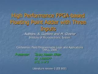
High Performance FPGA-based Floating Point Adder with Three Inputs
This paper presents a novel architecture for a three-input floating point adder optimized for FPGA implementation, specifically for applications involving Discrete Wavelet Transform (DWT). The design adheres to the IEEE 754 standard and utilizes a 5-stage pipeline architecture to enhance performance. Key components include a mantissa comparator, zero logic detection, an exponent difference calculation, and normalization stages. Performance results demonstrate operational speeds significantly higher than existing solutions, with achieved frequencies of 105 MHz and 143 MHz on Xilinx Virtex2 devices.

High Performance FPGA-based Floating Point Adder with Three Inputs
E N D
Presentation Transcript
High Performance FPGA-based Floating Point Adder with Three Inputs Authors: A. Guntoro and M. Glesner Institute of Microelectronic System Conference: Field Programmable Logic and Applications (FPL), 2008 Presenter: Tareq Hasan Khan ID: 11083577 ECE, U of S Literature review-2 (EE 800)
Outline • IEEE 754 Standard • Floating point addition algorithm • Proposed three input floating point adder • Overall architecture • Brief description of each stage • Results • Conclusion
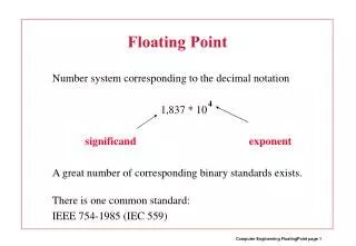
IEEE 754 Standard • Issued by IEEE in the year 1985 • Covers different types of floating point format • Single • Double… etc • In radix-2, floating point number can be written as (-1)s x 1.f x 2e where, s = sign bit, f = mantissa, e = biased exponent
Floating point addition algorithm • Calculate the exponent difference. • Align the mantissa by shifting the mantissa with the lower exponent to the right. • Add/sub both mantissas depending on the sign bits. • Perform the Leading-One Detection (LOD) to determine the location of the first logic one. • Normalize and round the result.
Outline • IEEE 754 Standard • Floating point addition algorithm • Proposed three input floating point adder • Overall architecture • Brief description of each stage • Results • Conclusion
Proposed three input floating point adder architecture • Used in lifting based Discrete Wavelet Transform (DWT) • 5 stage pipeline • Unique research
Stage 1 • Mantissa Comparator:compares the two mantissas Ma and Mb and latches both mantissas • Zero logic:detects if the corresponding input is zero. • Exponent difference:computes the two differences between Ea and Eb (i.e Ea − Eb and Eb − Ea).
Stage 2 • Shift, swap, add guard block • shift the mantissa with the smaller exponent to the right with the amount determined by the exponent selector block. • Swaps the mantissas when (Ma < Mb and Ea = Eb) or (Ea < Eb) is true. • The hidden bit and the guard bits are appended, resulting in fractions Fa and Fb. • If a zero number is detected, the corresponding fractions will be set to zero. • Exponent difference block computes the two differences between Ed and Ec • Mc is latched in Register
Stage 3 • Add/sub and shift • The fractions Fa and Fb are added/subtracted depending on the sign difference (Sa XOR Sb), resulting the fraction Fab. • If the exponent Ec is greater than max(Ea, Eb), the result will be shifted to the right. • Shift and add guard • It prepares the mantissa Mc. If Ecis less than max(Ea, Eb), Mc will be shifted right instead. • The hidden bit and the guard bits are appended to Mc, resulting in fraction Fc.
Stage 4 • Operand swap and add/sub block • Swaps the operands Fab and Fc if necessary (notice that both operands have the same exponent). • It performs the addition or subtraction, which results Fr. • Leading One Petection (LOP) block • Predicts the first occurrence of the “logic one” directly from the operands. One-bit inaccuracy might occur, so it gives two values at the output • Exponent adjustment blockprepares the dominant exponent by simply adding two to the larger exponent (i.e. max(Ea, Eb, Ec) + 2). Because three addition/subtraction arithmetic operations might have an increase of exponent by two.
Stage 5 • LOP error is corrected from Fr • Normalization is basically a shiftleft block with the amount given by the corrected LOP value • The overflow and underflow detector verifies if the resulting fraction and exponent lay outside the floating-point range. • The rounding logic implements two rounding mechanisms: rounding to zero and rounding to nearest.
Outline • IEEE 754 Standard • Floating point addition algorithm • Proposed three input floating point adder • Overall architecture • Brief description of each stage • Results • Conclusion
Result Config. Format: exponent–mantissa–guard Xilinx Virtex2 XC2V2000-5 Xilinx Virtex2 XC2VP30-7
Result • Slice usage • Slightly higher compared to Malik, but still lower compared to the IP core. • Operating speeds • Higher than both the IP core and Malik on most of the target devices. About 19% speed gain can be achieved on Virtex2Pro and 22% on Virtex2 compared to Malik. • Addition of three floating-point • The architectures from IP core and Malik will consume at least twice as many slices and will have a 10-level pipeline stage.
Conclusion • Design of a 3 input floating point adder • 5 stage pipeline • Can be operated on Xilinx Virtex2 XC2V2000-5 and Virtex2Pro XC2VP30-7 at 105 MHz and 143 MHz respectively.