Download
1 / 10
100 likes | 244 Vues
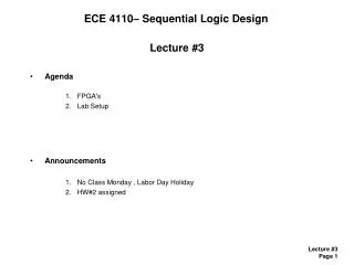
ECE 4110– Sequential Logic Design. Lecture #34 Agenda Timing Clocking Techniques Announcements n/a. Timing.

E N D
ECE 4110– Sequential Logic Design Lecture #34 • Agenda • Timing • Clocking Techniques • Announcements • n/a
Timing • Pipelined Logic- we can break up the combinational logic delay by inserting registers between each level.- this reduces combinational logic delay, but we don't get the information right awayLatency - the time you need to wait for the data to come out of the pipelineActivity - the percentage of time that the signals are switching. More activity means that the pipeline will continually output data and Latency is not a problem. - if the signals are not very active (i.e, a transition here and there), then the pipeline overhead might not be worth it.
Timing • Pipelined Logic- for a pipeline to improve data throughput, the timing for a burst of data must be better than: (Torig)·(n) < (Tpipe)·(Lc + n -1) where: Torig = period of fastest clock frequency with unbroken combinational logic Tpipe = improved period when pipelining (typically considers one logic level) Lc = the number of latency clock cycles necessary for the data to appear at the output of the pipeline n = number of consecutive pieces of meaningful data- In an ideal case, the data inputs would always be meaningful (which is sometimes the case) This would mean that you would only incur Lc once at the start-up of the system- However, some protocols start and stop the system to save power. This means you continually have to incur Lc each time you start the system.
Clocking • Clocking- in a synchronous system, the clock is the trigger for all data movement & manipulation - the clock is assumed to arrive at the CLK inputs of each Flip-Flop at the same time- in reality, this is not the case. Physical factors create mismatches in when the clock arrives at each register input- this timing error is called "Clock Skew"- this can be caused by: 1) Trace mismatching 2) Process variation - traces are wider on one side = different RC 3) Power Supply Variation - clocks distributed using buffers are sensitive to power
Clocking • Clock Trees- an H-Tree is a technique to distribute clocks to all regions of a chip with equal delay- the rule is that each time an H is added to any end-node, an H is added at every other end-node.- this keeps the RC's the same for all paths
w s t h Clocking • Clock Buffering (Clock Repeating)- as traces get small, their Resistance and Capacitance changes- we use a "Scaling Factor" (S) to describe the change in characteristics as we scale IC feature sizes- S is > 1 and typically between 1 and 2 (if S=2, then we reduce all sizes by 50%) Before After QuantityScalingScaling Width w w’ = w/S Spacing s s’ = s/S Thickness t t’ = t/S Interlayer oxide height h h’ = h/S
h t h w Clocking • Clock Buffering (Clock Repeating)- we can use S to see how the RC delay of traces scales- interconnect delay can be considerable and dominating in modern IC's Resistance scales following : S2 Horrible!!! Capacitance scales following : 1 OK Delay scales following : S2 Horrible!!!
h t h w Clocking • Clock Buffering (Clock Repeating)- R & C delay is also proportional to the Length of a trace (L) R = L·(/t·w) C = L·(rw/h)int RC L2- this means there is a quadratic dependency between delay and trace length- this is a major problem in clock trees L
Clocking • Clock Buffering (Clock Repeating)- a technique to break up the delay of long traces is to insert "repeaters"- each repeater and trace segment has a fixed delay- this allows the total delay of the trace to scale linearly ttotal = n·(trepeater + trace) where n = the number of repeater/trace segments ttrace = delay of the trace segment trepeater = delay of the buffer- optimal sizing is where ttrace= trepeater
Clocking • Clock Buffering (Clock Repeating)- advantages of clock repeating: 1) linear scaling of delay with length 2) signal strength at end-node is good- disadvantages of clock repeating power consumption of active buffers