Advances in Microelectronics Stitching Techniques and Power Optimization
130 likes | 230 Vues
Explore the progress meeting discussing the implementation of stitching in microelectronics chips, with focus on blading space and scribe lanes. Delve into power consumption calculations, perpendicular memory cells, and timing code distribution for enhanced performance. Discover advancements in power optimization and chip layout designs.

Advances in Microelectronics Stitching Techniques and Power Optimization
E N D
Presentation Transcript
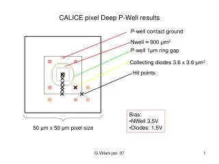
Terra-Pixel APS for CALICE Progress meeting 10th Nov 2005 Jamie Crooks, Microelectronics/RAL
21mm Reticle How stitching works 27mm Blading space Scribe lanes
Stitching 4 x 6.2cm chips 1 x 13cm chip 5 x 5.6cm chips
Test structures? Need to fully dice? • 150um scribe lanes, could remain uncut… • Could cut a 13x13cm area from the wafer containing an array of chips with 150um spacings? • Yield? • Bonding / alignment complications? • Full 13cm readout lengthSmaller arrays for tests
108 Chips @ 5.6cm = 22 wafers 27 chips = 1.51m 4 chips = 22.4cm 12 chips = 1.56m 2 chips = 26cm 24 Chips @ 13cm = 24 wafers
PCB concerns ~100 LVDS pairs to FPGA Power planes, local decoupling Differential clock and control signals? Well designed clock distribution! Synchronisation? PLLs? Serial chain of all chips on- board for setup programming? Optical links along PCB? Less control signals the better! x27 rows? LVDS data LVDS data Clk, Control signals (common)
Data Access times • Per physics event • 2000 hits per layer • If these were all on a single chip… • @6.6Mhz, reading 2 values per pixel, takes 600uS to read those 2k pixels • How many “physics events” per train?
Power Consumption • Example: Single clock line driven to every pixel… • Calculation for a 1mm square, 50um pixels • 0.22pF estimated line capacitance (per col) • Clock rate 6.6Mhz (150ns repetition) at 3.3V • 319uW per square mm • Allowing 2% duty cycle, 6.4uW per sq mm (for one global signal to 400 pixels)
Perpendicular memory cells? • Parallel write • Serial read • + less sense amps • + serial out consistent • with link to FPGA • + Din/out perpendicular • Need 16 1-bit shift register • cells in every cell instead of 1 • Different column lengths depending on hits 1 2 3 4 1 2 3 4
Perpendicular memory cells 2? Parallel read Serial write Timing code is shifted along through pixels Or generated from single bit shift registers in neighbour pixels Reduced power load to distribute timing code Added complexity/scrambled data Would require some set-up time before pulse train 1 2 1 2
“Current Focus” • Register selection for write and read access • Suitable low-power clocked comparator with adjustable threshold/offset • Analog circuits in the pixel • Continuous reset mode • How to “add” multiple pixel values • DRAM Cells • Stacked capacitors are possible • Simulate and compare lifetime with “physics events” statistics to establish suitability of dynamic storage • Sample layouts to indicate cell size