Download
1 / 21
210 likes | 290 Vues
Comprehensive update on cooling and powering of the focus coil system at STFC – RAL including successful operation, issues faced, and steps taken for resolution. Detailed overview of cooling tests, LN2 inputs, issues during powering, and quench detection system tripping. In-depth analysis of the current team's efforts and progress made. Challenges, solutions, and future plans discussed.

E N D
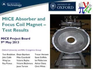
Focus Coil UpdateCM35 Roy Preece STFC - RAL 14th February 2013
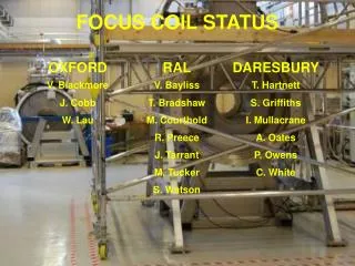
The Current Team • Tom Bradshaw, Mike Courthold, Vicky Bayliss • John Cobb, Victoria Blackmore, Wing Lau • Steve Griffiths, Chris White, Trevor Hartnett, Ian Mullacrane, Adrian Oates, Pete Owens, Phil Warburton.
Sections • Cooling • Issues • Powering • Plans
Cooling • Test of the cryo coolers – 23rd November • Successful operation with first and second stage cooling. • Water chiller operated well • Confidence for starting the LN2 cooling • LN2 cooling – 26th November • Goal of 90K for the cold mass • LN2 cooling during the day • Pump and purge with He gas 3 times • Cryo cooler operate overnight. • Allow second stage of cold head to warm to 80K before re-starting LN2 input. • Final LN2 input 6th December – Cold mass at 90K • Coolers operating – 6th December • He gas regulated to input 1.05 bar to the cold mass Helium circuit • Approximately 20 bar of gas has been used (not lost) • Cold mass and second stage heads at temperatures that indicate Helium being condensed.
Cooling LN2 Cooling (Cryo cooler overnight) Coolers Operating Coolers Operating Cold Mass temps LN2 Cooling Radiation Shield 2nd Stage Head Cryo cooler operation check
Cooling - Full • Gas input from bottle pack – 1.05 bar • Level sensor operating but not able to communicate with the control system. • System cooling over the Christmas period • By the New year the level was reported as being 100%. • Pressure feedback heater systems operating with a regulation of 0.005 bar. • Level reduced to 80% using the pressure regulation heaters and the exhaust poppet valve. • Pressure regulated at 1.14 bar with a gas bottle backup set to 1.05 bar. • Good news : Easily demonstrated zero boil off conditions • Good news : Control system and monitoring works well
Issues during cooling • Over the holiday period there were issues surrounding the remote monitoring of the system • This was complicated by the loss of air conditioning in a room somewhere …. – this took down several of the PPD computers • Other software issues concerned versions of the software running on different computers • Although the data was archived it was not always accessible through the archiver. • Where are the computers that we are using located ? What networks are they on? Who is responsible for this kit ? Over the holiday period it was difficult to resolve these issues
Review and Issues • A pre powering review was held on the 8th Jan. • Risk and method statements nominally agreed (some amendments) • Pressure relief mainly reliant on the bursting disc. Relief valve with higher flow rate added to the system. • Ready to go forward with final preparations and powering. • Issues • Current lead heaters not working • Found to have very high resistance to new installed. • ON / OFF reporting on control screen sorted. • Connection to ground found on voltage tap • Problem rectified and full connectivity check carried out.
Powering • Powering of the coils started on 11th Jan • Quench detection system tripping due to “Step function” from the power supply controller, AMI 430. • Maximum current output set to 5A and QD system taken out of the control loop. • Current of 5A in the coils but, voltage spikes evident while the controller is trying to control the current. 0.14T seen at the centre of the magnet bore. • The cause of the “Step function” is unknown so AMI are contacted for assistance. • Testing operations were stopped at this point and the magnet was left in a safe but cold state.
Powering • DL engineers on site at RAL working on the controller problem today. (More up to date information in the meeting) • Earthing of the controller checked as per AMI suggestion with no change. • Further investigations into addition earth loops • Change the controller for a spare unit to ascertain if the same issue is seen. • Blah Blah Blah Blah………. • None of this was needed because the problem was found to be the instructions from AMI are incorrect and at the wrong end of the scale. 95% stability setting required NOT 20%.
Powering • Magnet powered to 50A and held steady for a short period. • A quench was induced at his point. • Induced quench to exercise the dump resistor pack under the magnet • Pressure rise to 1.45 bar • Bursting disc did not fracture
Powering • Magnet refilled and further powering runs carried out. • Quench at 104A • Much debate on the reason for the quench • Threshold of the Quench detection boards at 20mV • Consensus is that the quench was due to “noise” on the system triggering the QD system. • Channel comparing the coils raised to 500mV • During the next powering run care was taken to ramp slowly and observe any noise and spikes as viewed on a scope attached to the amplified output of the QD channel. • Solenoid mode of 114A achieve and held for 2 hours (31st Jan) • Successfully ramped down and left in a stable state.
Powering • 11th Feb – magnet re-cabled to be in Flip mode. • PICO logging system attached to the Quench detection system to read actual voltage on each channel. • Second channel board setup to be at the 500mV threshold level. • Problem found with the board so removed. • 12th Feb – Powering in Flip mode started. • Powering in 50A steps, holding at each step to reduce the Helium pressure. • Steps to 50A and 100A show no problems or issues. • During ramping to target of 150A, quench occurred at 145A. • Reason at the moment is unknown. • During investigation damage to channel 1 board of the QD system found. • One of the PICO loggers has also been damaged. • How has a very large voltage reached the PICO and QD board???
Powering • Investigations by Trevor and Chris are underway, reasons and findings as soon as possible.
Plans • Identify reason for the quench and burnt tracks. • Electronics failure or training • Complete the Flip mode powering – 225A • Test fit the Hydrogen turret and flange. • Pump down Hydrogen side insulation volume. • Acceptance of the Magnet • Field mapping of the magnet by CERN team • Move magnet to hall – early April. • 2nd Focus Coil arrival at RAL around August / September