Download

1 / 37
480 likes | 1.05k Vues
Geometric Tolerances & Dimensioning. Based on notes of Prof McCarthy, University of California, Irvine. Tool Design, 3331 Dr Simin Nasseri Southern Polytechnic State University. Content. Overview Form tolerances Orientation tolerances Location tolerances Wrapping up.

E N D
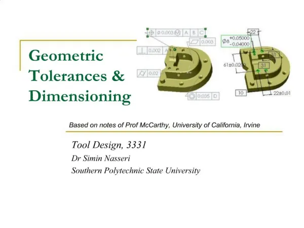
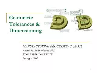
Geometric Tolerances & Dimensioning Based on notes of Prof McCarthy, University of California, Irvine Tool Design, 3331 Dr Simin Nasseri Southern Polytechnic State University
Content • Overview • Form tolerances • Orientation tolerances • Location tolerances • Wrapping up Southern Polytechnic State University
ANSI Y14.5-1994 Standard This standard establishes uniform practices for defining and interpreting dimensions, and tolerances, and related requirements for use on engineering drawings. The figures in this presentation are taken from Bruce Wilson’s Design Dimensioning and Tolerancing. Southern Polytechnic State University
Geometric Tolerancing • What is Geometric tolerancing used for? Geometric Tolerancing is used to specify the shape of features. Things like: • Straightness • Flatness • Circularity • Cylindricity • Angularity • Profiles • Perpendicularity • Parallelism • Concentricity And More... Southern Polytechnic State University
Overview of Geometric Tolerances • Geometric tolerances define the shape of a feature as opposed to its size. • We will focus on three basic types of dimensional tolerances: • Form tolerances: straightness, circularity, flatness, cylindricity; • Orientation tolerances; perpendicularity, parallelism, angularity; • Position tolerances: position, symmetry, concentricity. Southern Polytechnic State University
Symbols for Geometric Tolerances Form Orientation Position Southern Polytechnic State University
Most Common Symbols Southern Polytechnic State University
Feature Control Frame A geometric tolerance is prescribed using a feature control frame. It has three components: 1. the tolerance symbol, 2. the tolerance value, 3. the datum labels for the reference frame. Southern Polytechnic State University
Feature Control Frame • How do you read this feature control frame? “The specified feature must lie perpendicular within a tolerance zone of 0.05 diameter at the maximum material condition, with respect to datum axis C.” In other words, this places a limit on the amount of variation in perpendicularity between the feature axis and the datum axis. In a drawing, this feature control frame would accompany dimensional tolerances that control the feature size and position. Southern Polytechnic State University
Reference Frame A reference frame is defined by three perpendicular datum planes. The left-to-right sequence of datum planes defines their order of precedence. Southern Polytechnic State University
Order of Precedence • The part is aligned with the datum planes of a reference frame using 3-2-1 contact alignment. • 3 points of contact align the part to the primary datum plane; • 2 points of contact align the part to the secondary datum plane; • 1 point of contact aligns the part with the tertiary datum plane Southern Polytechnic State University
Using a Feature as a Datum A feature such as a hole, shaft, or slot can be used as a datum. In this case, the datum is the theoretical axis, centerline, or center plane of the feature. The “circle M” denotes the datum is defined by the Maximum Material Condition (MMC) given by the tolerance. Southern Polytechnic State University
Material Conditions • Maximum Material Condition (MMC): The condition in which a feature contains the maximum amount of material within the stated limits. e.g. minimum hole diameter, maximum shaft diameter. • Least Material Condition (LMC): The condition in which a feature contains the least amount of material within the stated limits. e.g. maximum hole diameter, minimum shaft diameter • Regardless of Feature Size (RFS): This is the default condition for all geometric tolerances. No bonus tolerances are allowed and functional gauges may not be used. Southern Polytechnic State University
Material Conditions • ANSI Y14.5M RULE #1: • A dimensioned feature must have perfect form at its maximum material condition. • This means: • A hole is a perfect cylinder when it is at its smallest permissible diameter, • A shaft is a perfect cylinder when at its largest diameter. • Planes are perfectly parallel when at their maximum distance. ANSI Y14.5M RULE #2: If no material condition is specified, then it is “regardless of feature size.” Southern Polytechnic State University
Material Conditions • Which one is which? Southern Polytechnic State University
Straightness of a Shaft • A shaft has a size tolerance defined for its fit into a hole. A shaft meets this tolerance if at every point along its length a diameter measurement fall within the specified values. • This allows the shaft to be bent into any shape. A straightness tolerance on the shaft axis specifies the amount of bend allowed. Southern Polytechnic State University
Straightness of a Shaft • Add the straightness tolerance to the maximum shaft size (MMC) to obtain a “virtual condition” Vc, or virtual hole, that the shaft must fit to be acceptable. Southern Polytechnic State University
Straightness of a Hole • The size tolerance for a hole defines the range of sizes of its diameter at each point along the centerline. This does not eliminate a curve to the hole. • The straightness tolerance specifies the allowable curve to the hole. • Subtract the straightness tolerance from the smallest hole size (MMC) to define the virtual condition Vc, or virtual shaft, that must fit the hole for it to be acceptable. Southern Polytechnic State University
Straightness of a Center Plane • The size dimension of a rectangular part defines the range of sizes at any cross-section. • The straightness tolerance specifies the allowable curve to the entire side. • Add the straightness tolerance to the maximum size (MMC) to define a virtual condition Vc that the part must fit into in order to meet the tolerance. Southern Polytechnic State University
Flatness, Circularity and Cylindricity The flatness tolerance defines a distance between parallel planes that must contain the highest and lowest points on a face. Southern Polytechnic State University
Flatness, Circularity and Cylindricity The circularity tolerance defines a pair of concentric circles that must contain the maximum and minimum radius points of a circle. Southern Polytechnic State University
Flatness, Circularity and Cylindricity The cylindricity tolerance defines a pair of concentric cylinders that much contain the maximum and minimum radius points along a cylinder. Southern Polytechnic State University
Parallelism Tolerance A parallelism tolerance is measured relative to a datum specified in the control frame. If there is no material condition (ie. regardless of feature size), then the tolerance defines parallel planes that must contain the maximum and minimum points on the face. Southern Polytechnic State University
Parallelism Tolerance • If MMC is specified for the tolerance value: • • If it is an external feature, then the tolerance is added to the maximum dimension to define a virtual condition that the part must fit; • • If it is an internal feature, then the tolerance is subtracted to define the maximum dimension that must fit into the part. Southern Polytechnic State University
Perpendicularity A perpendicular tolerance is measured relative to a datum plane. It defines two planes that must contain all the points of the face. A second datum can be used to locate where the measurements are taken. Southern Polytechnic State University
Perpendicular Shaft, Hole, and Center Plane • Shaft: The maximum shaft size plus the tolerance defines the virtual hole. Southern Polytechnic State University
Perpendicular Shaft, Hole, and Center Plane Hole: The minimum hole size minus the tolerance defines the virtual shaft. Southern Polytechnic State University
Perpendicular Shaft, Hole, and Center Plane Plane: The tolerance defines the variation of the location of the center plane. Southern Polytechnic State University
Angularity • An angularity tolerance is measured relative to a datum plane. • It defines a pair planes that must • contain all the points on the angled face of the part, or • if specified, the plane tangent to the high points of the face. Southern Polytechnic State University
Position Tolerance for a Hole • The position tolerance for a hole defines a zone that has a defined shape, size, location and orientation. • It has the diameter specified by the tolerance and extends the length of the hole. • Basic dimensions locate the theoretically exact center of the hole and the center of the tolerance zone. • Basic dimensions are measured from the datum reference frame. Southern Polytechnic State University
Material Condition Modifiers MMC: If the tolerance zone is prescribed for the maximum material condition (smallest hole). Then the zone expands by the same amount that the hole is larger in size. Use MMC for holes used in clearance fits. Southern Polytechnic State University
Material Condition Modifiers RFS: No material condition modifier means the tolerance is “regardless of feature size.” Use RFS for holes used in interference or press fits. Southern Polytechnic State University
Position Tolerance on a Hole Pattern A composite control frame signals a tolerance for a pattern of features, such as holes. • The first line defines the position tolerance zone for the holes. • The second line defines the tolerance zone for the pattern, which is generally smaller. Southern Polytechnic State University
Datum Reference in a Composite Tolerance A datum specification for the pattern only specifies the orientation of the pattern tolerance zones. Primary datum specified. Southern Polytechnic State University
Datum Reference in a Composite Tolerance No datum for the pattern Southern Polytechnic State University
Summary • Geometric tolerances are different from the tolerances allowed for the size of feature, they specify the allowable variation of the shape of a feature. • There are three basic types of geometric tolerances: Form, Orientation and Position tolerances. • Geometric tolerances are specified using a control frame consisting of a tolerance symbol, a tolerance value and optional datum planes. • Material condition modifiers define the condition at which the tolerance is to be applied. If the maximum material condition is specified, then there is a “bonus tolerance” associated with a decrease in material. • 1. The form of a feature is assumed to be perfect at its maximum material condition. • 2. If no material condition is specified, then it is regard less of feature size. Southern Polytechnic State University
Additional materials • http://www.engineersedge.com/tolerance__calc_menu.shtml • http://www.engineersedge.com/fixed_fastener.htm • http://www.engineersedge.com/gdt.htm Southern Polytechnic State University