Download

1 / 60
630 likes | 962 Vues
UEE-604 PEM Fuel Cell. Pradip Majumdar Department of Mechanical Engineering Northern Illinois University DeKalb, IL 60115. PEMFC Operation. Schematic of Tri-layer Fuel Cell. Electrochemical Half Reactions. Anode. Cathode. Overall. Cell Polarization Curve.

E N D
UEE-604PEM Fuel Cell Pradip Majumdar Department of Mechanical Engineering Northern Illinois University DeKalb, IL 60115
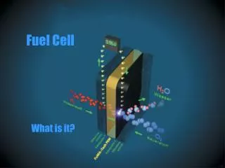
PEMFC Operation Schematic of Tri-layer Fuel Cell Electrochemical Half Reactions Anode Cathode Overall
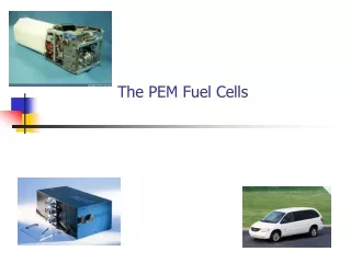
Applications Vehicle transportation Smaller scale stationary power generation Auxiliary Power Units (APUs) Portable powers for electronics POLYMER ELECTROLYTE MEMBRANE (PEM) Fuel Cell • Attractive Features • Higher power density • Compactness • Lower weight • lower temperature range • Good start-stop • Quicker response to load variations.
Major Challenges For Commercialization • Improve cell efficiency • Reduce cost (Material and Manufacturing) • Increase reliability and durability of some of the key components such as - Membrane Electrode Assembly (MEA) - Bipolar Plates - Heat and Water Management - Seals
Major Technical Issues • Current polymer membrane is limited to operations below 90 C due to the requirement of hydration. • Poor water distribution in the membrane. - leads to drying at anode side and flooding at cathode side. - increase losses at high current density. • Poor gas concentration distribution at the reaction surfaces. • Use of expensive catalyst. - need reduced catalyst loading - need alternate, less expensive catalyst (Other than Platinum)
Recent Research and Development Activities • Scalable and improved fabrication processes for production of membranes, electrodes, MEAs and Bipolar plates. • Catalyst and supports with reduced metal loading, increased activity, durability, and lower cost. • Use of non-precious metal catalyst for reduced cost. • Membrane with increased ionic conductivity, reduced thickness and durability. • Bipolar plates with improved gas flow channels, higher conductivity, lower weight and cost, negligible corrosion.
Identify new materials, new design and fabrication methods for Membrane Cathode catalyst and support Bipolar plates Subsystems and subsystems components Develop high-temperature and low relative humidity polymer electrolyte membrane. - extend temperature range to 120 C and above - lower relative humidity at 80 C ( < 10%) - improve tolerance for impurities (Enhanced CO tolerance) Future Research Focus
Membrane Additional evaluation of Nafion membrane at different temperatures. Operation at higher temperatures for better thermal management - up to 120 C for vehicle applications - above 120 C for stationary application. Membrane that can operate at lower humidity content ( <10%). Thinner membrane - better water distribution - reduced resistance
Catalyst Minimize precise metal loading. Develop thinner catalyst coating. New metal catalyst Develop newer design for Active Reaction Zone
Bipolar Plates • Higher performance gas flow channel design. • Lower weight and volume. • Higher structural strength. • Higher corrosion resistance. • High volume fabrication process.
Proton Exchange Membrane (PEM) • Major requirements • High ionic conductivity • Lower electronic conductivity • Higher stability and durability • Lower fuel crossover • Higher structural strength • Ease of manufacturability
Polymer Electrolyte Membrane • The purpose of the polymer electrolyte is to transport the proton from anode to cathode side. • Different trade names for polymer membrane (e.g. Nafion) • The polymer membrane such as Nafion is designed to include large amount hydrated regions through which proton can migrate efficiently. • Base material is the Sulfonated Fluoropolymer (Fluoroethylene)
Polymer Exchange Membrane (PEM) Developed First by General Electric (1962) for Gemini Project. - Polymer solid membrane - Polystyrene sulfonic acid membrane. - 70 C operating temperature - Needed humidification for water management. - Durability problem.
Proton Exchange Membrane (PEM) Dow Chemical developed experimental membrane (1988) - Equivalent weight (EW): 800 - Showed improved hydrogen Fuel cell performance - Demonstrated durability over 10,000 hrs
Dupont Polymer Membrane (1970-Present) • Perfluorosulfonic acid membrane • (Sulphonatedfluoroethylene) • Includes PTFE (polytetrafluoroethylene) as support. • - operating temperature: 80 C • - Nafion – 115/117: • Equivalent weight (EW): 900-1100 : • Thickness: 178-micron • - Nafion – 105: • Equivalent weight (EW): 1000 : • Thickness: 127-micron
Nafion Membrane Construction • Starting structure is a polymer – Polyethylene • Modified by replacing Hydrogen with Fluorine. • Leads to the structure Polyterafluoroethylene (PTFE) • The basic PTFE structure is Sulphonated by adding a Sulphonic acid chain
Typical Polymer Structure in Nafion • The basic PTFE structure is Sulphonated by adding a Sulphonic acid chain . • The use of Sulphonic acid creates a hydrophyllic regions within a hydrophobic substance. • Hydrated regions are created for keeping a weak attraction between the hydrogen ion and the sulfonate ion.
Major Characteristics of Nafion • Nafion is characterized as a water-filled clusters, interconnected by channels. • The surface of the clusters and channels are the Sulfonate ions. • The mobile liquid – phase is composed of hydrogen ion and water: • Since proton conductivity depends on water concentration in the membrane, it is essential that the membrane is sufficiently hydrated.
Electrode and Gas Diffusion Layer (GDL) • Reactions at the electrode-membrane interface are surface phenomena, and require large exposed solid surface area. • Electrodes are made in the form porous structures to achieve large surface area. • The pore structure are made of a micro-porous carbon cloth or paper through which reactant gas diffuses towards the interface. - Some popular band are Toray, CARBEL and E-TAK
Catalyst • A catalyst layer is added to enhance the electrochemical reaction and reduce activation overpotential. • Small platinum catalyst particles are supported on larger and finely divided carbon Particles. • The reaction regionis characterized by the active surface area where electrode, electrolyte, catalyst are present : - Expressed as catalyst mass of per unit area: • A carbon-based power XC-72 commonly used.
Electrode Designs I. Separate Electrode - Carbon supported catalyst is fixed on the GDL. - The electrode is than hot pressed on the membrane to form membrane Electrode Assembly (MEA) II. Integral Membrane-Electrode - Carbon supported catalyst particles are fixed on the membrane surface. - A gas diffusion layer is then applied.
Electrode Designs • The carbon supported catalyst particles are impregnated into a thin layer of GDL. • Impregnation of electrode within thin layer of electrolyte membrane forming a three- phase active reaction zone or triple phase boundaries (TPB): Example: Kim et al. [1995] -Developed an Nafion impregnated electrodes with Platinum loading of and a Nafion content of • This is a very active area of research. • Needs microscopic/nanoscale simulation model for analysis and design of the structure.
Bipolar Plate Design MEA • Bipolar plates play a key role in the performance of the fuel cell. • Includes separated gas flow channels to supply reactant gasses as well as remove products to and from electrodes. • The flow field as well as the energy and mass transport in the gas channels effects - gas concentartion distribution - current density distribution - mass transport losses. • This is more critical for the operation of the fuel cell at higher current density. Bipolar Plates Tri-layer Membrane Electrode Assembly (MEA) with bipolar plates
Bi-Polar Plate Development • Bi-polar plates with different flow channel size, pattern and materials are analyzed to optimize the design in terms of enhanced performance and reduced weight and cost. • Fluid flow, heat and mass transfer analysis of a bipolar plate design with different flow channels is considered in this study. • Bi-polar plate made of different materials are evaluated for enhanced heat dissipation rate, structural integrity, reduced weight and machinability.
Design Options FDM Plastic Model • Thickness of the order of 2 - 5 mm • Includes channels for anode, cathode and • cooling/heating channels
Design Options outlet outlet inlet inlet Serpentine channel design Multiple channel design • Channel Patern - Straight parallel - multiple parallel - Square bends - Curvilinear bends • Channel sizes • - Macro channels • - Micro channels outlet Experimental model design
Multiple Channel Design Outer loop Inner loop Second loop Third loop Representation of Channels in Multiple Channels Bi-polar plate
Static Pressure Distribution Dynamic Pressure Distribution
Total pressure distribution along the channel Velocity vectors along the channel
Gibb’s Free Energy: Reversible Potential: Functional Relation for Gibb’s Energy = -2E-05*(T3) + 0.042*(T2) + 23.313*T – 239015 Alternate form of Reversible Potential
Nernst Equation Include effect of variation of concentration of change
Butler-Volmer Equation for Electrochemical Kinetics Thelocal current density distribution is calculated as using Butler-Volmer equation Where, i0 = exchange current density η = over potential n = number of electrons = Anodic transfer co-efficient = Cathodic transfer co-efficient
Transport Model Detail components of heat and mass fluxes across the PEM fuel cell that is being considered for the simulation model. Heat Flux Mass Flux
Gas Channels Mass and Momentum: Energy: Mass Concentration: Navier-Stokes Equation for velocity field
Gas Diffusion Layer Continuity: Momentum: Mass Transport: Heat Transfer:
Diffusion Coefficient Effective diffusion coefficient in a pore structure is given as Alternate form given by Bruggemann equations Binary diffusion coefficient is given based on Molecular diffusion Stefan-Maxwell equation for multicomponent diffusion
Polymer Membrane Water Transport Phenomena Water is transported by three mechanisms: - Electro-osmotic Drag due to the movement of proton - diffusion due to water concentration difference - Permeation due to pressure difference Ref: Verbrugge and Hill [1990], Springer et al. [1991], Bernadi and Verrugge [1992], Fuller and Newman [1993]
Water Transport Equation • Schlogl’s Equation (used by Bernadi and Verbrugge and Berning, Lu and Djilali (2002)) Takes into account of convection velocity given by electro-osmotic drag flux and pressure driven flux
Water Transport Equation Verbrugge and Hill (1990) used Nernst-Planck Equation to describe flux of species in the membrane pore liquid. Reduces to Schlogl equation for negligible diffusion For negligible pressure driven convection:
Transport Equation Mass Transport Heat Transport
Water Content (Springer et. al (1991) • Data available at 30C, but extended to use at 80 C. • Water content in Nafion -117 is given by sorption isotherm based on humidity condition and expressed as λ = 0.043 +(17.81*a) - (39.85*a2) + (36*a3) if a < 1 λ = 14 + (1.4*(a-1)) if a>1 Where a is the water activity defined as log10Psat = -2.1794 + (0.02953*T) - (9.1837e-5*T2) + (1.4454e-7*T3)
Proton Conductivity Proton Conductivity in Nafion-117 increases with water content and temperature and given as σ(λ) = - 0.0051638 + (0.00020217*λ) + (0.0022154*λ2) - (0.0002772*λ3) + (1.4657e-5*λ4) - (2.7746e-7*λ5)
Catalyst Layer • Negligible heat and mass transport resistance: • Consumption rates at catalyst-electrode interfaces are specified as follows: Cathode Layer: Anode Layer: Oxygen Gas Hydrogen Gas Water Generation Heat Generation
Bipolar Plate Energy Equation