Download
1 / 30
300 likes | 594 Vues
BUILT ENVIRONMENT COURSE. LESSON (2). LESSON (2)- A rchitectural D rawings. Introduction To Analytical Thinking & Drawing. B . Architectural Sketch. C . Structure Drawing. ARCHITECTURE DRAWING.

E N D
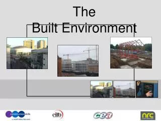
BUILT ENVIRONMENT COURSE LESSON (2)
LESSON (2)- Architectural Drawings Introduction To Analytical Thinking & Drawing B. Architectural Sketch C. Structure Drawing
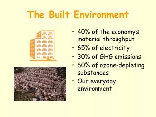
ARCHITECTURE DRAWING Anarchitecture drawingis a technical drawing of a building that falls within the definition of architecture. Architectural drawings are used by architects and others for a number of purposes: to develop a design idea into a coherent proposal, to communicate ideas and concepts, to convince clients of the merits of a design, to enable a building contractor to construct it. Architectural drawings are made according to a set of convention, which include particular views:- Site Plan Floor Plan Elevation Section Construction/Detailing Drawing. Every drawings must consist of the following components within the standard drawings format & sizes, (AO, A1, A2 and/or A3 if the project is small). Drawing Title Block Unit of measurement Scale Annotation Cross references
A. Analytical Thinking & Drawing Thinking Practically & Logically to conceptualize an end result to meet the criteria requirements. 2. Thinking of the best solution to resolve the problem. (Problem-solving skill) How You Could Think and Draw Analytically You must have the mind to visualize, articulate, conceptualize or solve both the complex and uncomplicated by making a good decisions that are sensible given with the available solution.
Example • When preparing the initial architecture layout plan with furniture in the drawings, the following information must be clear and adequate, including to consider all the logical and functional criterial and requirements. • - When planning a residential layout, you must ensure each area or room space, not just able to • accommodate the furniture, but also consider the human circulation or manoeuvring. area. • A door position must be in an appropriate swinging direction and position, so that it will not block or crash against the human traffic movement in the corridor. (especially at public area) and allow a basic clear space for manoeuvring. • When you are planning a kitchen layout, you must try to keep the kitchen appliances (cooker, sink & refrigerator. etc.) within a efficiency distance.
EXAMPLE (1) - Manoeuvring Space 1. To ensure the passage is clear with sufficient space – “C” for human traffic flow . (Fig. 18.1) , after the door has swing into the passage, Always try to swing inward instead, unless is for fire escape purpose. (Fig. 18.2) Fig. 18.1 Fig. 18.3 2. To ensure have minimum or sufficient clear space for human manoeuvring (when swinging backward) and allow the space for electrical switches adjacent to the door, including an appropriate or correct side of the door whenever is possible. (shown in dotted line – “B” ; Fig. 18.3. Fig. 18.2
EXAMPLE (2) - Functional and Practicality Fig. 17.1 Fig. 19.2 Fig. 19 Note:- The kitchen appliances are within the guided triangular formation or working area, easy to reach safety distance for the cooker hob away from the wet sink. (Fig. 19) The maneuvering space as shown in (Fig. 19.1 – 19.4), and the cabinet height are appropriate height for reaching and working. It is also called* ergonomic. Fig. 19.4 Fig. 19..3
Ergonomic An applied science concerned with the characteristics of people that need to be considered in the design of devices and system in order that people and things will interact effectively and safety. It also called human engineering.
B. Architectural Sketch Drawing A sketch is a quick execution, freehand drawing that is not intended as a finished work. In general, sketching is a quick way to record an idea for later use. Architect's sketches primarily serve as a way to try out different ideas and establish a composition before a more finished work. The finished work is expensive and time consuming, so it is important to resolve the design as fully as possible before construction work begins. Architectural Sketch Drawings create a quick diagram to develop the logic of a design or analyzing the solution. Sketching the form or shape of obtaining an initial building concept. Sketching alternative layout plan with furniture to obtain the best space planning result. Sketching the blown-up detailing to obtain the technical solution. Sketching the 3-Dimension or isometric during the meeting to obtain a better visual communication with some layman. Sketching the site condition to take down information from existing building such as measurement for detailing. Sketching of the Interior to review the internal structure, such as staircase & other spacing review.
“Therefore it is important to develop a good sketch drawing skill as an interpretation tool to provide better communication for all purpose and situation. Especially when site condition have changes or required to change and needed immediate solution for discussion, this is in fact also part of ‘Analytical Thinking”
Important of Architectural Sketch Drawings There are varieties technique for architectural sketches, depending on the elements that required to establish the concept or studying the detail drawings for construction etc.
Various type of diagrams and the purposes of the Sketch Drawings Example – (3) Fig. (B1) & (B2)is a simple sketch to review the propose building impact seating on the surrounding existing building. Fig. (A) Fig. (B1) Fig. (C) Fig. (C)is a simple sketch drawings, cross section of a building to review the ground level and the height of the building integration. Fig. (A)is a simple sketches drawings with diagrams and perspective created with the shape and form of the building, both in 2D and 3D. diagram. This is done during the very beginning stage for conceptualising the design Fig. (B2)
A more comprehensive of a schematic sketch drawings. Example – (4) Sketch of a “Building Plan” outline formation with shading line to demarcate the building shape. Sketch of the “Roof Plan” with shadow casting texture’s line works in dark tone to bring out the building impact. Sketch of the “Building Elevation “ with texture and shading to review the depth. Sketches the other 2D-Building Elevation with 3D-axonometric drawings to review the overall building look.
Example – (5) A more comprehensive of a schematic sketch drawings. Elevational View Fig. (D2) Perspective View Fig. (D3) Site Plan With Building Outline. Sectional View Fig. (D1)
Example – (6) Architectural Sketch Drawings. Sketch drawing was done to review the atrium structure impact and the volume of the space. Fig. (E.2) Fig.(E.1) Sketch drawing was done to review the stair-way structure and the internal space. Fig.(E.2) Fig.(E.2)
Example – (7) Sketch drawings, to review the roof and building façade concept. Architectural Sketch Drawings. Sketch drawings, to review the Building Feature and the Porte Entrance. Fig.(F.1) Fig.(F.2)
Example (8) – Free Hand Sketching to obtain the technical solution. (Fig. G.1 – G.3) Fig.(G.1) Fig.(G.2) Fig.(G.3)
Fig.(J.3) Example – (9) Various sketch of Architectural Interior. Fig.(J.2) Fig.(J.1)
Building Structure Building Structure Engineering includes all structural engineering related to the design of buildings. It is a branch of structural engineering closely affiliated with Architect. Therefore it is necessary to have a basic understanding of the structure drawings. What is Structural Drawing 1. Structural drawing, is a type of Engineering drawing, fundamentally, as a stable-assembly of structural elements designed and constructed to function as a whole in supporting and transmitting applied loads safety to the ground within the allowable stresses in the members. • 2. Structural Drawings are used to progress the Architect’s concept by specifying the shape and position of all parts of the structure – thus enabling the construction of that structure on site. Structural Drawings are also used for the preparation of the reinforcement drawings.
Understanding The Form Of Structure 1. Structural Drawing • Structural Drawings would typically include the following information: • a. Setting out dimensions for the concrete structure on site. • b. Plans, sections and elevations showing layout, dimensions and levels of all concrete • members within the structure. • c. Location of all holes, chases, pockets, fixings and other items affecting the concreting work. • d. Notes on specifications, finishes and all cross-references affecting the construction. • e. Provide the detailer with the layout and sectional information required to specify the length, • shape and number of each type of reinforcing bar. Generally, , most of the new building is using frame construction is more conventional where – walls either internal or external – do not necessary support the floors and roof, but are replaced by column and beam construction.
2. Reinforcement Drawings • Reinforcement drawings (or details), fully describe and locate all reinforcement in relation to the finished surface of the concrete and to any holes or fixings. As a general rule, circular holes up to 150mm diameter and rectangular holes up to (150 x 150)mm in slabs and walls need not to be shown on the reinforcement drawings. 3. Standard Details The detailer will often find that certain details occur regularly on a variety of jobs and some economy in detailing time may be effected by keeping a library of “Standard Details” for use whenever possible. Standard details might include:- Standard Notes Column bases and pile caps Concrete box culverts Expansion/Construction joint details, etc.
Structure Diagram Fig.(S1) Fig. S1,S2 & S3 – Both diagram showing the general Structure Frame of a building. Fig.(S3) Fig.(S2)
Fig. (S7) – Diagram showing Columns & Footing of a building. Structure Diagram Fig. (S4)– Diagram showing the general Structure Frame of a building. Fig.(S7)
Structure Diagram Fig. (S.9) - Structure drawing showing the Columns & Beams location. Fig. (S8) - Structure drawing showing the Footing.
1. Tied Column 2. Spiral Column Spiral column is also construction from reinforced concrete. In this type of column, longitudinal bars are confined within closely spaced and continuously wound spiral reinforcement. Spiral reinforcement provide lateral restrains (Poisson’s effect) and delays axial load failure (ductile). This type of column is commonly construction from reinforced concrete. Longitudinal reinforcement are confined within closely spaced tie reinforcement. It is estimated that 95% of all columns in buildings are tied Fig.(R.2) Fig.(R.1)
3. Composite Column When the longitudinal reinforcement is in the form of structural steel section or pipe with or without longitudinal bars, it is called as a composite column. This type of column have high strength with fairly small cross section, in addition to exhibit good fire performance. 4. What is Rebar? Steel reinforcement bars or rebar's are used to improve the tensile strength of the concrete, since concrete is very weak in tension, but is strong in compression. Steel is only used as rebar because elongation of steel due to high temperatures (thermal expansion coefficient) nearly equals to that of concrete. Fig.(R.3) Fig.(R.4)
6. Square or Rectangular Column They are generally used in the construction of buildings. It is much easier to construct and cast rectangular or square columns than circular ones because of ease of shuttering and to support it from collapsing due to pressure while the concrete is still in flow able form. Fig.(R.7) 5. T-Shape Column It is utilized based on design requirements of a structure. T-Shaped column is widely used in the construction of bridges. Fig.(R.5) 7. L-Shape Column Commonly, L-shaped column is utilized in the corners of the boundary wall and has similar characteristics of a rectangular or square column. Fig.(R.6)
Fig. (R.14) – Photos showing you the actual structure site works, the Rebar tying for the Columns & Beams.