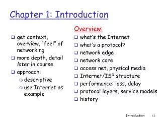
Chapter 1: Introduction
get context, overview, “feel” of networking more depth, detail later in course approach: descriptive use Internet as example. Overview: what’s the Internet what’s a protocol? network edge network core access net, physical media Internet/ISP structure performance: loss, delay

Chapter 1: Introduction
E N D
Presentation Transcript
get context, overview, “feel” of networking more depth, detail later in course approach: descriptive use Internet as example Overview: what’s the Internet what’s a protocol? network edge network core access net, physical media Internet/ISP structure performance: loss, delay protocol layers, service models history Chapter 1: Introduction Introduction
Chapter 1: roadmap 1.1 What is the Internet? 1.2 Network edge 1.3 Network core 1.4 Network access and physical media 1.5 Internet structure and ISPs 1.6 Delay & loss in packet-switched networks 1.7 Protocol layers, service models Introduction
millions of connected computing devices: hosts, end-systems PCs workstations, servers PDAs phones, toasters running network apps communication links fiber, copper, radio, satellite transmission rate = bandwidth routers: forward packets (chunks of data) router workstation server mobile local ISP regional ISP company network What’s the Internet: “nuts and bolts” view Introduction
protocolscontrol sending, receiving of msgs e.g., TCP, IP, HTTP, FTP, PPP Internet: “network of networks” loosely hierarchical public Internet versus private intranet Internet standards RFC: Request for comments IETF: Internet Engineering Task Force What’s the Internet: “nuts and bolts” view router workstation server mobile local ISP regional ISP company network Introduction
communication infrastructure enables distributed applications: Web, email, games, e-commerce, database., voting, file (MP3) sharing communication services provided to apps: connectionless connection-oriented What’s the Internet: a service view • cyberspace [Gibson]: “a consensual hallucination experienced daily by billions of operators, in every nation, ...." Introduction
human protocols: “what’s the time?” “I have a question” introductions … specific msgs sent … specific actions taken when msgs received, or other events network protocols: machines rather than humans all communication activity in Internet governed by protocols What’s a protocol? protocols define format, order of msgs sent and received among network entities, and actions taken on msg transmission, receipt Introduction
a human protocol and a computer network protocol: TCP connection response Get http://www.awl.com/kurose-ross Got the time? 2:00 <file> time What’s a protocol? Hi TCP connection req Hi Q: Other human protocols? Introduction
network edge: applications and hosts network core: routers network of networks access networks, physical media: communication links A closer look at network structure: Introduction
Chapter 1: roadmap 1.1 What is the Internet? 1.2 Network edge 1.3 Network core 1.4 Network access and physical media 1.5 Internet structure and ISPs 1.6 Delay & loss in packet-switched networks 1.7 Protocol layers, service models Introduction
end systems (hosts): run application programs e.g. Web, email at “edge of network” client/server model client host requests, receives service from always-on server e.g. Web browser/server; email client/server peer-peer model: minimal (or no) use of dedicated servers e.g. Gnutella, KaZaA The network edge: Introduction
Goal: data transfer between end systems handshaking: setup (prepare for) data transfer ahead of time Hello, hello back human protocol set up “state” in two communicating hosts TCP - Transmission Control Protocol Internet’s connection-oriented service TCP service[RFC 793] reliable, in-order byte-stream data transfer loss: acknowledgements and retransmissions flow control: sender won’t overwhelm receiver congestion control: senders “slow down sending rate” when network congested Network edge: connection-oriented service Introduction
Goal: data transfer between end systems same as before! UDP - User Datagram Protocol [RFC 768]: Internet’s connectionless service unreliable data transfer no flow control no congestion control App’s using TCP: HTTP (Web), FTP (file transfer), Telnet (remote login), SMTP (email) App’s using UDP: streaming media, teleconferencing, DNS, Internet telephony Network edge: connectionless service Introduction
Chapter 1: roadmap 1.1 What is the Internet? 1.2 Network edge 1.3 Network core 1.4 Network access and physical media 1.5 Internet structure and ISPs 1.6 Delay & loss in packet-switched networks 1.7 Protocol layers, service models Introduction
mesh of interconnected routers the fundamental question: how is data transferred through net? circuit switching: dedicated circuit per call: telephone net packet-switching: data sent thru net in discrete “chunks” The Network Core Introduction
End-end resources reserved for “call” link bandwidth, switch capacity dedicated resources: no sharing circuit-like (guaranteed) performance call setup required Network Core: Circuit Switching Introduction
each end-end data stream divided into packets user A, B packets share network resources each packet uses full link bandwidth resources used as needed Bandwidth division into “pieces” Dedicated allocation Resource reservation Network Core: Packet Switching resource contention: • aggregate resource demand can exceed amount available • congestion: packets queue, wait for link use • store and forward: packets move one hop at a time • transmit over link • wait turn at next link Introduction
Sequence of A & B packets does not have fixed pattern statistical multiplexing. In TDM each host gets same slot in revolving TDM frame. D E Packet Switching: Statistical Multiplexing 10 Mbs Ethernet C A statistical multiplexing 1.5 Mbs B queue of packets waiting for output link Introduction
Takes L/R seconds to transmit (push out) packet of L bits on to link or R bps Entire packet must arrive at router before it can be transmitted on next link: store and forward delay = 3L/R Example: L = 7.5 Mbits R = 1.5 Mbps delay = 15 sec Packet-switching: store-and-forward L R R R Introduction
Now break up the message into 5000 packets Packet Switching: Message Segmenting • Each packet 1,500 bits • 1 msec to transmit packet on one link • pipelining: each link works in parallel • Delay reduced from 15 sec to 5.002 sec Introduction
Goal: move packets through routers from source to destination we’ll study several path selection (i.e. routing)algorithms (chapter 4) datagram network: destination address in packet determines next hop routes may change during session analogy: driving, asking directions virtual circuit network: each packet carries tag (virtual circuit ID), tag determines next hop fixed path determined at call setup time, remains fixed thru call routers maintainper-call state Packet-switched networks: forwarding Introduction
Packet-switched networks Circuit-switched networks FDM TDM Datagram Networks Networks with VCs Network Taxonomy Telecommunication networks • Datagram network is not either connection-oriented • or connectionless. • Internet provides both connection-oriented (TCP) and • connectionless services (UDP) to apps. Introduction
Chapter 1: roadmap 1.1 What is the Internet? 1.2 Network edge 1.3 Network core 1.4 Network access and physical media 1.5 Internet structure and ISPs 1.6 Delay & loss in packet-switched networks 1.7 Protocol layers, service models Introduction
roughly hierarchical at center: “tier-1” ISPs (e.g., UUNet, BBN/Genuity, Sprint, AT&T), national/international coverage treat each other as equals NAP Tier-1 providers also interconnect at public network access points (NAPs) Tier-1 providers interconnect (peer) privately Internet structure: network of networks Tier 1 ISP Tier 1 ISP Tier 1 ISP Introduction
Tier-1 ISP: e.g., Sprint Sprint US backbone network Introduction
“Tier-2” ISPs: smaller (often regional) ISPs Connect to one or more tier-1 ISPs, possibly other tier-2 ISPs NAP Tier-2 ISPs also peer privately with each other, interconnect at NAP • Tier-2 ISP pays tier-1 ISP for connectivity to rest of Internet • tier-2 ISP is customer of tier-1 provider Tier-2 ISP Tier-2 ISP Tier-2 ISP Tier-2 ISP Tier-2 ISP Internet structure: network of networks Tier 1 ISP Tier 1 ISP Tier 1 ISP Introduction
“Tier-3” ISPs and local ISPs last hop (“access”) network (closest to end systems) Tier 3 ISP local ISP local ISP local ISP local ISP local ISP local ISP local ISP local ISP NAP Local and tier- 3 ISPs are customers of higher tier ISPs connecting them to rest of Internet Tier-2 ISP Tier-2 ISP Tier-2 ISP Tier-2 ISP Tier-2 ISP Internet structure: network of networks Tier 1 ISP Tier 1 ISP Tier 1 ISP Introduction
a packet passes through many networks! Tier 3 ISP local ISP local ISP local ISP local ISP local ISP local ISP local ISP local ISP NAP Tier-2 ISP Tier-2 ISP Tier-2 ISP Tier-2 ISP Tier-2 ISP Internet structure: network of networks Tier 1 ISP Tier 1 ISP Tier 1 ISP Introduction
Chapter 1: roadmap 1.1 What is the Internet? 1.2 Network edge 1.3 Network core 1.4 Network access and physical media 1.5 Internet structure and ISPs 1.6 Delay & loss in packet-switched networks 1.7 Protocol layers, service models Introduction
packets queue in router buffers packet arrival rate to link exceeds output link capacity packets queue, wait for turn packet being transmitted (delay) packets queueing (delay) free (available) buffers: arriving packets dropped (loss) if no free buffers How do loss and delay occur? A B Introduction
1. nodal processing: check bit errors determine output link transmission A propagation B nodal processing queueing Four sources of packet delay • 2. queuing • time waiting at output link for transmission • depends on congestion level of router Introduction
3. Transmission delay: R=link bandwidth (bps) L=packet length (bits) time to send bits into link = L/R 4. Propagation delay: d = length of physical link s = propagation speed in medium (~2x10⁸ m/sec) propagation delay = d/s transmission A propagation B nodal processing queueing Delay in packet-switched networks Note: s and R are very different quantities! Introduction
“Real” Internet delays and routes • What do “real” Internet delay & loss look like? • Traceroute program: provides delay measurement from source to router along end-end Internet path towards destination. For all i: • sends three packets that will reach router i on path towards destination • router i will return packets to sender • sender times interval between transmission and reply. 3 probes 3 probes 3 probes Introduction
“Real” Internet delays and routes traceroute: gaia.cs.umass.edu to www.eurecom.fr Three delay measurements from gaia.cs.umass.edu to cs-gw.cs.umass.edu 1 cs-gw (128.119.240.254) 1 ms 1 ms 2 ms 2 border1-rt-fa5-1-0.gw.umass.edu (128.119.3.145) 1 ms 1 ms 2 ms 3 cht-vbns.gw.umass.edu (128.119.3.130) 6 ms 5 ms 5 ms 4 jn1-at1-0-0-19.wor.vbns.net (204.147.132.129) 16 ms 11 ms 13 ms 5 jn1-so7-0-0-0.wae.vbns.net (204.147.136.136) 21 ms 18 ms 18 ms 6 abilene-vbns.abilene.ucaid.edu (198.32.11.9) 22 ms 18 ms 22 ms 7 nycm-wash.abilene.ucaid.edu (198.32.8.46) 22 ms 22 ms 22 ms 8 62.40.103.253 (62.40.103.253) 104 ms 109 ms 106 ms 9 de2-1.de1.de.geant.net (62.40.96.129) 109 ms 102 ms 104 ms 10 de.fr1.fr.geant.net (62.40.96.50) 113 ms 121 ms 114 ms 11 renater-gw.fr1.fr.geant.net (62.40.103.54) 112 ms 114 ms 112 ms 12 nio-n2.cssi.renater.fr (193.51.206.13) 111 ms 114 ms 116 ms 13 nice.cssi.renater.fr (195.220.98.102) 123 ms 125 ms 124 ms 14 r3t2-nice.cssi.renater.fr (195.220.98.110) 126 ms 126 ms 124 ms 15 eurecom-valbonne.r3t2.ft.net (193.48.50.54) 135 ms 128 ms 133 ms 16 194.214.211.25 (194.214.211.25) 126 ms 128 ms 126 ms 17 * * * 18 * * * 19 fantasia.eurecom.fr (193.55.113.142) 132 ms 128 ms 136ms trans-oceanic link * means no response (probe lost, router not replying) Introduction
Packet loss • queue (aka buffer) preceding link in buffer has finite capacity • when packet arrives to full queue, packet is dropped (aka lost) • lost packet may be retransmitted by previous node, by source end system, or not retransmitted at all Introduction
Chapter 1: roadmap 1.1 What is the Internet? 1.2 Network edge 1.3 Network core 1.4 Network access and physical media 1.5 Internet structure and ISPs 1.6 Delay & loss in packet-switched networks 1.7 Protocol layers, service models Introduction
Networks are complex! many “pieces”: hosts routers links of various media applications protocols hardware, software Question: Is there any hope of organizing structure of network? Or at least our discussion of networks? Protocol “Layers” Introduction
ticket (complain) baggage (claim) gates (unload) runway landing airplane routing ticket (purchase) baggage (check) gates (load) runway takeoff airplane routing airplane routing Organization of air travel • a series of steps Introduction
ticket (complain) baggage (claim) gates (unload) runway landing airplane routing ticket (purchase) baggage (check) gates (load) runway takeoff airplane routing airplane routing Organization of air travel: a different view Layers: each layer implements a service • via its own internal-layer actions • relying on services provided by layer below Introduction
Layered air travel: services Counter-to-counter delivery of person+bags baggage-claim-to-baggage-claim delivery people transfer: loading gate to arrival gate runway-to-runway delivery of plane airplane routing from source to destination Introduction
airplane routing airplane routing airplane routing Distributed implementation of layer functionality ticket (complain) baggage (claim) gates (unload) runway landing airplane routing ticket (purchase) baggage (check) gates (load) runway takeoff airplane routing arriving airport Departing airport intermediate air traffic sites Introduction
Why layering? Dealing with complex systems: • explicit structure allows identification, relationship of complex system’s pieces • layered reference model for discussion • modularization eases maintenance, updating of system • change of implementation of layer’s service transparent to rest of system • e.g., change in gate procedure doesn’t affect rest of system • layering considered harmful? Introduction
application: supporting network applications FTP, SMTP, STTP transport: host-host data transfer TCP, UDP network: routing of datagrams from source to destination IP, routing protocols link: data transfer between neighboring network elements PPP, Ethernet physical: bits “on the wire” application transport network link physical Internet protocol stack Introduction
Each layer: distributed “entities” implement layer functions at each node entities perform actions, exchange messages with peers network link physical application transport network link physical application transport network link physical application transport network link physical application transport network link physical Layering: logical communication Introduction
E.g.: transport take data from app add addressing, reliability check info to form “datagram” send datagram to peer wait for peer to ack receipt analogy: post office network link physical application transport network link physical application transport network link physical application transport network link physical application transport network link physical data data data ack Layering: logical communication transport transport Introduction
network link physical application transport network link physical application transport network link physical application transport network link physical application transport network link physical data data Layering: physical communication Introduction
M M H H H H H H H H H H H H t t t n l n l t n t n t M M M M application transport network link physical application transport network link physical M M Protocol layering and data Each layer takes data from above • adds header information to create new data unit • passes new data unit to layer below source destination message segment datagram frame Introduction