Download
1 / 15
150 likes | 184 Vues
Explore resistors in series and parallel, Kirchhoff’s rules for circuit analysis, and problem-solving techniques. Learn about current distribution, voltage calculations, and the application of Junction and Loop rules.

E N D
26-2 Resistors in Series and in Parallel Example 26-5: Current in one branch. What is the current through the 500-Ω resistor shown? (Note: This is the same circuit as in the previous problem.) The total current in the circuit was found to be 17 mA.
26-2 Resistors in Series and in Parallel Conceptual Example 26-6: Bulb brightness in a circuit. The circuit shown has three identical lightbulbs, each of resistance R. (a) When switch S is closed, how will the brightness of bulbs A and B compare with that of bulb C? (b) What happens when switch S is opened? Use a minimum of mathematics in your answers.
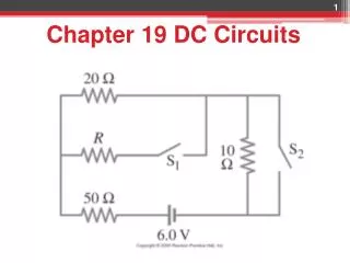
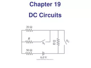
26-2 Resistors in Series and in Parallel Example 26-8: Analyzing a circuit. A 9.0-V battery whose internal resistance r is 0.50 Ω is connected in the circuit shown. (a) How much current is drawn from the battery? (b) What is the terminal voltage of the battery? (c) What is the current in the 6.0-Ω resistor?
26-3 Kirchhoff’s Rules Some circuits cannot be broken down into series and parallel connections. For these circuits we use Kirchhoff’s rules. Junction rule: The sum of currents entering a junction equals the sum of the currents leaving it I3=I1+I2
26-3 Kirchhoff’s Rules Loop rule: The sum of the changes in potential around a closed loop is zero.
Loop Rule Traveling around the loop from a to b • In (a), the resistor is traversed in the direction of the current, the potential across the resistor is –IR • In (b), the resistor is traversed in the direction opposite of the current, the potential across the resistor is +IR
Loop Rule, final • In (c), the source of emf is traversed in the direction of the emf (from – to +), the change in the electric potential is +ε • In (d), the source of emf is traversed in the direction opposite of the emf (from + to -), the change in the electric potential is -ε
Circuit Analysis Principles Keep in mind that: I through each element Current (charge) splits at junctions Current (charge) is the same in series Apply junction rule Vacross each element or set Voltages add in series Voltages are same in parallel Voltages around a loop sum to zero (loop rule)
26-3 Kirchhoff’s Rules Example 26-9: Using Kirchhoff’s rules. Calculate the currents I1, I2, and I3 in the three branches of the circuit in the figure.
Problem 31 31. (II) (a) What is the potential difference between points a and d in Fig. 26–49 (similar to Fig. 26–13, Example 26–9), and (b) what is the terminal voltage of each battery?
26-3 Kirchhoff’s Rules Problem Solving: Kirchhoff’s Rules • Label each current, including its direction. • Identify unknowns. • Apply junction and loop rules; you will need as many independent equations as there are unknowns. • Solve the equations, being careful with signs. If the solution for a current is negative, that current is in the opposite direction from the one you have chosen.
26-4 Series and Parallel EMFs; Battery Charging EMFs in series in the same direction: total voltage is the sum of the separate voltages.
26-4 Series and Parallel EMFs; Battery Charging EMFs in series, opposite direction: total voltage is the difference, but the lower-voltage battery is charged. Example :”car alternator”
26-4 Series and Parallel EMFs; Battery Charging EMFs in parallel only make sense if the voltages are the same; this arrangement can produce more current than a single emf.