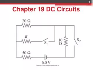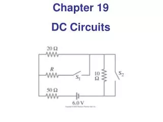
Series and Parallel Resistor Circuits
Learn about resistors in series and parallel circuits, calculate voltage drops and current, enhance knowledge of equivalent resistance. Improvement in conceptual understanding.


Series and Parallel Resistor Circuits
E N D
Presentation Transcript
26-2 Resistors in Series and in Parallel A series connection has a single path from the battery, through each circuit element in turn, then back to the battery.
26-2 Resistors in Series The current through each resistor is the same; the voltage depends on the resistance. The sum of the voltage drops across the resistors equals the battery voltage:
26-2 Resistors in Series From this we get the equivalent resistance (that single resistance that gives the same current in the circuit): Unless an internal resistance r is specified assume V constant.
9 V ConcepTest 26.1a Series Resistors I 1)12 V 2)zero 3)3 V 4) 4 V 5) you need to know the actual value of R Assume that the voltage of the battery is 9 V and that the three resistors are identical. What is the potential difference across each resistor?
9 V ConcepTest 26.1a Series Resistors I 1)12 V 2)zero 3)3 V 4) 4 V 5) you need to know the actual value of R Assume that the voltage of the battery is 9 V and that the three resistors are identical. What is the potential difference across each resistor? Since the resistors are all equal, the voltage will drop evenly across the 3 resistors, with 1/3 of 9 V across each one. So we get a 3 V drop across each.
R1 = 4 W R2 = 2 W 12 V ConcepTest 26.1b Series Resistors II 1)12 V 2)zero 3)6 V 4) 8 V 5) 4 V In the circuit below, what is the voltage across R1?
R1 = 4 W R2 = 2 W 12 V ConcepTest 26.1b Series Resistors II 1)12 V 2)zero 3)6 V 4) 8 V 5) 4 V In the circuit below, what is the voltage across R1? The voltage drop across R1 has to be twice as big as the drop across R2. This means that V1 = 8 V and V2 = 4 V. Or else you could find the current I = V/R = (12 V)/(6 W) = 2 A, and then use Ohm’s law to get voltages. Follow-up: What happens if the voltage is 24 V?
26-2 Resistors in Parallel A parallel connection splits the current; the voltage across each resistor is the same:
26-2 Resistors in Parallel The total current is the sum of the currents across each resistor: ,
26-2 Resistors in Parallel An analogy using water may be helpful in visualizing parallel circuits. The water (current) splits into two streams; each falls the same height, and the total current is the sum of the two currents. With two pipes open, the resistance to water flow is half what it is with one pipe open.
R2 = 2 W R1 = 5 W 10 V ConcepTest 26.2a Parallel Resistors I 1)10 A 2)zero 3)5 A 4) 2 A 5) 7 A In the circuit below, what is the current through R1?
R2 = 2 W R1 = 5 W 10 V ConcepTest 26.2a Parallel Resistors I 1)10 A 2)zero 3)5 A 4) 2 A 5) 7 A In the circuit below, what is the current through R1? The voltage is the same (10 V) across each resistor because they are in parallel. Thus, we can use Ohm’s law, V1 = I1R1to find the current I1 = 2 A. Follow-up: What is the total current through the battery?
ConcepTest 26.2b Parallel Resistors II 1)increases 2)remains the same 3)decreases 4) drops to zero Points P and Q are connected to a battery of fixed voltage. As more resistors R are added to the parallel circuit, what happens to the total current in the circuit?
ConcepTest 26.2b Parallel Resistors II 1)increases 2)remains the same 3)decreases 4) drops to zero Points P and Q are connected to a battery of fixed voltage. As more resistors R are added to the parallel circuit, what happens to the total current in the circuit? As we add parallel resistors, the overall resistance of the circuit drops. Since V = IR, and V is held constant by the battery, when resistance decreases, the current must increase. Follow-up: What happens to the current through each resistor?
26-2 Resistors in Series and in Parallel Conceptual Example 26-2: Series or parallel? (a) The light bulbs in the figure are identical. Which configuration produces more light? (b) Which way do you think the headlights of a car are wired? Ignore change of filament resistance R with current. Note: brightness is proportional to power
26-2 Resistors in Series and in Parallel Conceptual Example 26-2: Series or parallel? (a) The light bulbs in the figure are identical. Which configuration produces more light? (b) Which way do you think the headlights of a car are wired? Ignore change of filament resistance R with current.
26-2 Resistors in Series and in Parallel Conceptual Example 26-3: An illuminating surprise. A 100-W, 120-V lightbulb and a 60-W, 120-V lightbulb are connected in two different ways as shown. In each case, which bulb glows more brightly? Ignore change of filament resistance with current (and temperature).
26-2 Resistors in Series and in Parallel Conceptual Example 26-3: An illuminating surprise.
26-2 Resistors in Series and in Parallel Example: Current in one branch. What is the current through the 500-Ω resistor shown?
26-2 Resistors in Series and in Parallel Example 26-8: Analyzing a circuit. A 9.0-V battery whose internal resistance r is 0.50 Ω is connected in the circuit shown. (a) How much current is drawn from the battery? (b) What is the terminal voltage of the battery? Note: slight error in figure and text
26-3 Kirchhoff’s Rules Some circuits cannot be broken down into series and parallel connections. For these circuits we use Kirchhoff’s rules.
26-3 Kirchhoff’s Rules Junction rule: The sum of currents entering a junction equals the sum of the currents leaving it.
26-3 Kirchhoff’s Rules Loop rule: The sum of the changes in potential around a closed loop is zero.
26-3 Kirchhoff’s Rules • Problem Solving: Kirchhoff’s Rules • Label each current, including its direction. • Identify unknowns. • Apply junction and loop rules; you will need as many independent equations as there are unknowns. Each new junction or loop must include a new element. • Solve the equations, being careful with signs. If the solution for a current is negative, that current is in the opposite direction from the one you have chosen.
ConcepTest 26.10Kirchhoff’s Rules 1) both bulbs go out 2) intensity of both bulbs increases 3) intensity of both bulbs decreases 4) A gets brighter and B gets dimmer 5) nothing changes The lightbulbs in the circuit are identical. When the switch is closed, what happens?
ConcepTest 26.10Kirchhoff’s Rules 24 V Follow-up:What happens if the bottom battery is replaced by a 24 V battery? 1) both bulbs go out 2) intensity of both bulbs increases 3) intensity of both bulbs decreases 4) A gets brighter and B gets dimmer 5) nothing changes The lightbulbs in the circuit are identical. When the switch is closed, what happens? When the switch is open, the point between the bulbs is at 12 V. But so is the point between the batteries. If there is no potential difference, then no current will flow once the switch is closed!! Thus, nothing changes.
26-3 Kirchhoff’s Rules Example: Using Kirchhoff’s rules. Calculate the currents I1, I2, and I3 in the three branches of the circuit in the figure.
1 I2 2 6 V 2 V 2 V 4 V I3 I1 1 3 ConcepTest 26.12 MoreKirchhoff’s Rules 1) 2 – I1 – 2I2 = 0 2) 2 – 2I1 – 2I2– 4I3= 0 3) 2 – I1 – 4 – 2I2= 0 4) I3 – 4 – 2I2 + 6= 0 5) 2 – I1 – 3I3– 6= 0 Which of the equations is valid for the circuit below?
1 I2 2 6 V 2 V 2 V 4 V I3 I1 1 3 ConcepTest 26.12 MoreKirchhoff’s Rules 1) 2 – I1 – 2I2 = 0 2) 2 – 2I1 – 2I2– 4I3= 0 3) 2 – I1 – 4 – 2I2 = 0 4) I3 – 4 – 2I2 + 6= 0 5) 2 – I1 – 3I3– 6= 0 Which of the equations is valid for the circuit below? Eq. 3 is valid for the left loop: The left battery gives +2 V, then there is a drop through a 1 W resistor with current I1 flowing. Then we go through the middle battery (but from + to – !), which gives –4 V. Finally, there is a drop through a 2 W resistor with current I2.
26-4 Series and Parallel EMFs EMFs in parallel only make sense if the voltages are the same; this arrangement can produce more current than a single emf.
26-5 Circuits Containing Resistor and Capacitor (RC Circuits) When the switch is closed, the capacitor will begin to charge. As it does, the voltage across it increases, and the current through the resistor decreases.
26-5 RC Circuits To find the voltage as a function of time, we write the equation for the voltage changes around the loop: Since Q = dI/dt, we can integrate to find the charge as a function of time:
26-5 RC Circuits The voltage across the capacitor is VC = Q/C: The quantity RC that appears in the exponent is called the time constant of the circuit:
26-5 RC Circuits The current at any time t can be found by differentiating the charge:
26-5 RC Circuits Example 26-11: RC circuit, with emf. The capacitance in the circuit shown is C = 0.30 μF, the total resistance is 20 kΩ, and the battery emf is 12 V. Determine (a) the time constant, (b) the maximum charge the capacitor could acquire, (c) the time it takes for the charge to reach 99% of this value, (d) the current I when the charge Q is half its maximum value, (e) the maximum current, and (f) the charge Q when the current I is 0.20 its maximum value.
26-5 RC Circuits If an isolated charged capacitor is connected across a resistor, it discharges:
26-5 RC Circuits Once again, the voltage and current as a function of time can be found from the charge: and
26-5 RC Circuits Example 26-12: Discharging RC circuit. In the RC circuit shown, the battery has fully charged the capacitor, so Q0 =CE. Then at t = 0 the switch is thrown from position a to b. The battery emf is 20.0 V, and the capacitance C = 1.02 μF. The current I is observed to decrease to 0.50 of its initial value in 40 μs. (a) What is the value of Q, the charge on the capacitor, at t = 0? (b) What is the value of R? (c) What is Q at t = 60 μs?
26-5 RC Circuits Conceptual Example 26-13: Bulb in RC circuit. In the circuit shown, the capacitor is originally uncharged. Describe the behavior of the lightbulb from the instant switch S is closed until a long time later.
26-6 Electric Hazards Most people can “feel” a current of 1 mA; a few mA of current begins to be painful. Currents above 10 mA may cause uncontrollable muscle contractions, making rescue difficult. Currents around 100 mA passing through the torso can cause death by ventricular fibrillation. Higher currents may not cause fibrillation, but can cause severe burns. Household voltage can be lethal if you are wet and in good contact with the ground. Be careful!
Summary of Chapter 26 • A source of emf transforms energy from some other form to electrical energy. • A battery is a source of emf in parallel with an internal resistance. • Resistors in series:
Summary of Chapter 26 • Resistors in parallel: • Kirchhoff’s rules: • Sum of currents entering a junction equals sum of currents leaving it. • Total potential difference around closed loop is zero.
Summary of Chapter 26 • RC circuit has a characteristic time constant: • To avoid shocks, don’t allow your body to become part of a complete circuit.