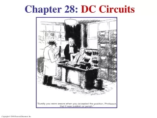
Chapter 19 DC Circuits
Chapter 19 DC Circuits. Units of Chapter 19. EMF and Terminal Voltage Resistors in Series and in Parallel Kirchhoff’s Rules EMFs in Series and in Parallel; Charging a Battery Circuits Containing Capacitors in Series and in Parallel. Units of Chapter 19.

Chapter 19 DC Circuits
E N D
Presentation Transcript
Chapter 19 DC Circuits
Units of Chapter 19 • EMF and Terminal Voltage • Resistors in Series and in Parallel • Kirchhoff’s Rules • EMFs in Series and in Parallel; Charging a Battery • Circuits Containing Capacitors in Series and in Parallel
Units of Chapter 19 • RC Circuits – Resistor and Capacitor in Series • Electric Hazards • Ammeters and Voltmeters
19.1 EMF and Terminal Voltage Electric circuit needs battery or generator to produce current – these are called sources of emf. Battery is a nearly constant voltage source, but does have a small internal resistance, which reduces the actual voltage from the ideal emf: (19-1)
19.1 EMF and Terminal Voltage This resistance behaves as though it were in series with the emf.
19.2 Resistors in Series and in Parallel A series connection has a single path from the battery, through each circuit element in turn, then back to the battery.
19.2 Resistors in Series and in Parallel The current through each resistor is the same; the voltage depends on the resistance. The sum of the voltage drops across the resistors equals the battery voltage. (19-2)
19.2 Resistors in Series and in Parallel From this we get the equivalent resistance (that single resistance that gives the same current in the circuit). (19-3)
19.2 Resistors in Series and in Parallel A parallel connection splits the current; the voltage across each resistor is the same:
19.2 Resistors in Series and in Parallel The total current is the sum of the currents across each resistor:
19.2 Resistors in Series and in Parallel This gives the reciprocal of the equivalent resistance: (19-4)
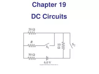
Find the voltage across the 18Ω Resistor and the current flowing through it. Fig. P18.6, p.578
Find the equivalent resistor. • Find the voltage across the 20Ω resistor • and the current flowing through it. Fig. P18.9, p.578
a) Find the equivalent resistor. b) Find the voltage across the 6Ω resistor. Fig. P18.13, p.579
Statement of Kirchhoff’s Rules • Junction Rule • The sum of the currents entering any junction must equal the sum of the currents leaving that junction • A statement of Conservation of Charge • Loop Rule • The sum of the potential differences across all the elements around any closed circuit loop must be zero • A statement of Conservation of Energy
High Voltage Low Voltage Fig. 18.13a, p. 564
Low Voltage High Voltage Fig. 18.13b, p. 564
Low Voltage High Voltage Fig. 18.13c, p. 564
High Voltage Low Voltage Fig. 18.13d, p. 564
Apply Kirchoff’s • first law • I1 + I2 = I3 • 2. Apply Kirchoff’s • second law • Write two loop • equations Fig. 18.15, p.566
Write Two Loop Equations summing voltage drops and rises in a Clockwise direction around the loop • Voltage rises are positive • Voltage drops are negative Junction c current equation I1 + I2 = I3 Loop befc -14 + 6I1 – 10 – 4I2 = 0 Loop abcd 10 -6I1 -2I3 = 0
19.3 Kirchhoff’s Rules For these circuits we use Kirchhoff’s rules. Junction rule: The sum of currents entering a junction equals the sum of the currents leaving it.
Capacitors in Parallel(have the same voltage across them) Q1 = C1ΔV Q2 = C2ΔV Q1 + Q2 = Qtot = C1ΔV + C2ΔV = (C1+ C2)ΔV for capacitors in parallel Ceq= C1+ C2 Ex. 16.5 p.512
Capacitors in Series(have the same charge on each plate) ΔV = Q Ceq ΔVtot = ΔV1 + ΔV2 Q = Q1 + Q2 Ceq C1 C2 But Q=Q1= Q2 for capacitors in series 1 = 1 + 1 Ceq C1 C2 Ceq = C1C2 C1 + C2 Ex. 16.6 & 7 p. 515
Energy Stored in a Capacitor • Energy stored = ½ Q ΔV • From the definition of capacitance, this can be rewritten in different forms Q = CV
19.6 RC Circuits – Resistor and Capacitor in Series When the switch is closed, the capacitor will begin to charge.
19.6 RC Circuits – Resistor and Capacitor in Series The voltage across the capacitor increases with time: This is a type of exponential.
19.6 RC Circuits – Resistor and Capacitor in Series The charge follows a similar curve: This curve has a characteristic time constant: (19-7)
19.6 RC Circuits – Resistor and Capacitor in Series If an isolated charged capacitor is connected across a resistor, it discharges:
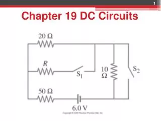
19.3 Kirchhoff’s Rules Some circuits cannot be broken down into series and parallel connections.
19.3 Kirchhoff’s Rules Loop rule: The sum of the changes in potential around a closed loop is zero.
19.3 Kirchhoff’s Rules • Problem Solving: Kirchhoff’s Rules • Label each current. • Identify unknowns. • Apply junction and loop rules; you will need as many independent equations as there are unknowns. • Solve the equations, being careful with signs.
19.4 EMFs in Series and in Parallel; Charging a Battery EMFs in series in the same direction: total voltage is the sum of the separate voltages
19.4 EMFs in Series and in Parallel; Charging a Battery EMFs in series, opposite direction: total voltage is the difference, but the lower-voltage battery is charged.
19.4 EMFs in Series and in Parallel; Charging a Battery EMFs in parallel only make sense if the voltages are the same; this arrangement can produce more current than a single emf.
19.5 Circuits Containing Capacitors in Series and in Parallel Capacitors in parallel have the same voltage across each one:
19.5 Circuits Containing Capacitors in Series and in Parallel In this case, the total capacitance is the sum: (19-5)
19.5 Circuits Containing Capacitors in Series and in Parallel Capacitors in series have the same charge:
19.5 Circuits Containing Capacitors in Series and in Parallel In this case, the reciprocals of the capacitances add to give the reciprocal of the equivalent capacitance: (19-6)
19.7 Electric Hazards Even very small currents – 10 to 100 mA can be dangerous, disrupting the nervous system. Larger currents may also cause burns. Household voltage can be lethal if you are wet and in good contact with the ground. Be careful!
19.7 Electric Hazards A person receiving a shock has become part of a complete circuit.
19.7 Electric Hazards Faulty wiring and improper grounding can be hazardous. Make sure electrical work is done by a professional.
19.7 Electric Hazards The safest plugs are those with three prongs; they have a separate ground line. Here is an example of household wiring – colors can vary, though! Be sure you know which is the hot wire before you do anything.
19.8 Ammeters and Voltmeters An ammeter measures current; a voltmeter measures voltage. Both are based on galvanometers, unless they are digital. The current in a circuit passes through the ammeter; the ammeter should have low resistance so as not to affect the current.
19.8 Ammeters and Voltmeters A voltmeter should not affect the voltage across the circuit element it is measuring; therefore its resistance should be very large.
19.8 Ammeters and Voltmeters An ohmmeter measures resistance; it requires a battery to provide a current
19.8 Ammeters and Voltmeters If the meter has too much or (in this case) too little resistance, it can affect the measurement.
Summary of Chapter 19 • A source of emf transforms energy from some other form to electrical energy • A battery is a source of emf in parallel with an internal resistance • Resistors in series: