Download
1 / 21
210 likes | 235 Vues
Dive into AC circuits with a focus on reactance calculations, voltage analysis, and phasor diagrams. Learn the principles behind inductors and resistors, including calculating maximum current and voltage across components. Explore the relationship between current and voltage in series circuits, and uncover the role of capacitors in AC circuits. Practice using Kirchoff's law and delve into the complexities of AC circuits.

E N D
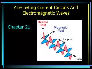
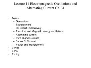
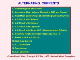
PHY-2054 J. B. Bindell Chapter 22 – Alternating CurrentPart 2
Monday – Continue with Chapter 22 • Wednesday – • Hope to return the exams. • more of the same • Friday – • Quiz • No 10:30 AM office hours (sorry) • Next Monday – Probably a problem solving session at 7:00AM. Confirmation later in the week. the future
result - inductor I is the MAXIMUM current in the circuit.
Resistor inductor (wL) looks like a resistance XL=wL Reactance - OHMS comparing
For the inductor FOR THE RESISTOR Let’s put these together.
slightly confusing point We will always use the CURRENT as the basis for calculations and express voltages with respect to the current. What that means?
direction wt wt
remember for ac series circuits The current is the same throughout the series circuit. The Maximum Current “I” is also the same for all series circuit elements.
Compute the reactance of a 0.450 H inductor at frequencies of 60.0 Hz
In the circuit below, R=30 W and L= 30 mH. If the angular frequency • of the 60 volt AC source is is 3 K-Hz • WHAT WE WANT TO DO: • calculate the maximum current in the circuit • calculate the voltage across the inductor • Does Kirchoff’s Law Work? E=60V w=3 KHZ R=30 W L= 30 mH
R=30W XL=wL=90W The instantaneous voltage across each element is the PROJECTION of the MAXIIMUM voltage onto the horizontal axis! This is the SAME as the sum of the maximum vectors projected onto the horizontal axis. E=60V I w=3 KHZ R=30 W L= 30 mH wt
Source voltage leads the current by the angle f. I wt E=60V w=3 KHZ R=30 W L= 30 mH
The drawing is obviously NOT to scale. I wt E=60V w=3 KHZ R=30 W L= 30 mH
What about the capacitor?? Without repeating what we did, the question is what function will have a Df/Dt = cosine? Obviously, the sine! So, using the same process that we used for the inductor,
The voltage lags the current by 90 deg I and V are represented on the same graph but are different quantities. NOTICE THAT
An AC source with ΔVmax = 125 V and f = 25.0 Hz is connected between points a and d in the figure. Calculate the maximum voltages between the following points: (a) a and b 62.8 V(b) b and c 45.6 V(c) c and d 154 V(d) b and d 108 V
ac circuits look complicated http://www.ngsir.netfirms.com/englishhtm/RLC.htm