Download
1 / 89
910 likes | 1.77k Vues
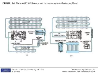
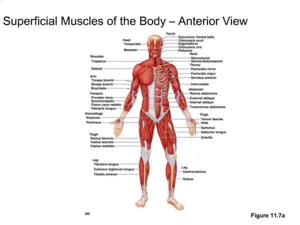
FIGURE 8-1 Both TXV (a) and OT (b) A/C systems have five major components. (Courtesy of ACDelco).

E N D
FIGURE 8-1 Both TXV (a) and OT (b) A/C systems have five major components. (Courtesy of ACDelco)
FIGURE 8-2 Some of the variety of compressors a and l use a crankshaft; b, d, e, f, h, and i use a swash plate; c and g use a wobble plate with a variable stroke; e and m use a Scotch yoke; j and k use a plain wobble plate; and n is a vane compressor. (Courtesy of Everco Industries)
FIGURE 8-2 (CONTINUED) Some of the variety of compressors a and l use a crankshaft; b, d, e, f, h, and i use a swash plate; c and g use a wobble plate with a variable stroke; e and m use a Scotch yoke; j and k use a plain wobble plate; and n is a vane compressor. (Courtesy of Everco Industries)
FIGURE 8-3 This compressor is compatible with both R-134a and R-12 and is available in three different capacities or displacements, with one of seven different clutch configurations of either 12 or 24 volts, and with one of seven different rear head and line port configurations. (Courtesy of Seltec)
FIGURE 8-4 Rotation of the swash plate causes these double pistons to move through the suction and discharge strokes. Evaporator pressure fills the cylinders with refrigerant during the suction stroke. This refrigerant is pumped into the high side during the discharge stroke.
FIGURE 8-5 The displacement of a compressor is determined by the length of the stroke, diameter of the cylinders (bore), and number of cylinders.
FIGURE 8-6 A 2-cylinder compressor creates 2 large pumping pulses per revolution. A 10-cylinder compressor (same displacement) creates 10 smaller pulses; its operation is much smoother.
FIGURE 8-7 The Tecumseh (left) and York 2-cylinder,inline compressors were very common at one time. (Courtesy of Four Seasons)
FIGURE 8-8 A York 209 compressor (a) and a more compact mini series (b). York compressors can be identified by part number and crankshaft appearance (c). (Courtesy of Four Seasons)
FIGURE 8-8 (CONTINUED) A York 209 compressor (a) and a more compact mini series (b). York compressors can be identified by part number and crankshaft appearance (c). (Courtesy of Four Seasons)
FIGURE 8-9 A Tecumseh HG 850 or HG 1000 (a) is identified by part number. The HG 500 (b) is a single-cylinder compressor. (Courtesy of Four Seasons)
FIGURE 8-10 The two pistons in a Chrysler V compressor are arranged in a V shape. (Courtesy of ACDelco)
FIGURE 8-11 An R-4 compressor has two pairs of pistons that are driven by a Scotch yoke. (Courtesy of Visteon)
FIGURE 8-12 Note how rotation of the swash plate causes the pistons to slide through their strokes. Balls and shoes act as bearings between the swash plate and pistons. (Courtesy of Zexel USA Corporation)
FIGURE 8-13 The suction (a) and discharge (b) crossover circuits of a swash-plate compressor transfer refrigerant to and from the cylinders at the other end. Note how oil from the suction crossover lubricates the internal parts. (Reprinted with permission of General Motors Corporation)
FIGURE 8-14 A disassembled view of an A-6 compressor; this compressor was very popular during the 1960s, 1970s, and early 1980s. (Courtesy of ACDelco)
FIGURE 8-15 A disassembled view of a DA-6 compressor; this compressor replaced the A-6. (Courtesy of ACDelco)
FIGURE 8-16 Three versions of Denso compressors; note the different mounting bosses. (Courtesy of Four Seasons)
FIGURE 8-17 This Zexel compressor uses a swash-plate design. (Courtesy of Zexel USA Corporation)
FIGURE 8-18 Rotation of the drive hub causes the wobble action of the wobble plate and forces the single pistons to move through their strokes. (Courtesy of Zexel USA Corporation)
FIGURE 8-19 A variable displacement compressor can change the angle of the wobble plate and piston stroke. This angle is changed by a control valve that senses evaporator pressure, which in turn changes wobble chamber pressure. (Courtesy of Zexel USA Corporation)
FIGURE 8-20 Two of the DA6 and HR6 versions of the front head (left and center) and a view of the rear head (right). (Courtesy of ACDelco)
FIGURE 8-21 The piston stroke of this variable displacement compressor is controlled by crankcase pressure, which is adjusted using an electric solenoid (right). (Courtesy of Toyota Motor Sales USA, Inc.)
FIGURE 8-22 A compact variable displacement compressor. Note the pistons use a spherical bearing to connect to the wobble plate. (Courtesy of Delphi Corp., all rights reserved)
FIGURE 8-23 An electric compressor with its bright orange HV wires for power (a). Another compressor that combines a belt driven scroll with an electrically driven scroll (b).
FIGURE 8-24 The decal on this compressor identifies the type (SDB709) and the serial number. Note also that it uses a seven-groove, multi-V clutch, four mounting bolts, and vertical-pad service ports at the side.
FIGURE 8-25 A cutaway (a) and exploded (b) view of a clutch assembly showing the major parts. (a. Courtesy of Warner Electric; b. Courtesy of ACDelco)
FIGURE 8-26 In most clutches, the coil is stationary, secured to the compressor (a). In a rotating field clutch, the coil is built into the rotor, and a brush assembly is used to conduct electricity into and out of the coil (b). (Courtesy of Warner Electric)
FIGURE 8-27 Most compressors use three-piece clutches as shown here (a). The rotor is driven by a belt, the hub drives the compressor shaft, and the coil is secured to the compressor (b). (Courtesy of Warner Electric)
FIGURE 8-27 (CONTINUED) Most compressors use three-piece clutches as shown here (a). The rotor is driven by a belt, the hub drives the compressor shaft, and the coil is secured to the compressor (b). (Courtesy of Warner Electric)
FIGURE 8-28 The magnetic flux path is from the coil and through the metal of the rotor and clutch hub. When it meets a pole groove, it travels from the hub to the rotor or vice versa, which increases the clutch holding power.
FIGURE 8-29 The plastic shield on the front of this clutch hub (a) is a thermal fuse; if it gets too hot, it will melt and cause the clutch to fail before compressor damage occurs (b). (Courtesy of Warner Electric)
FIGURE 8-30 This damper drive is a one-piece pulley and hub. Torque is transferred from the pulley through the rubber damper (a), and another damper-drive type uses torque-limiting metal fingers that will shear if the compressor should seize.
FIGURE 8-31 The shaft seal must keep refrigerant from escaping out the front of the compressor. Most compressors have an oil flow routed to them to reduce wear and improve the sealing action. (Courtesy of Toyota Motor Sales USA, Inc.)
FIGURE 8-32 Many compressors use a two-piece seal with a rotating carbon seal and a stationary seal. (Courtesy of ACDelco)
FIGURE 8-33 Some newer compressors use a stationary lip seal that seals against the rotating shaft. (Courtesy ACDelco)
FIGURE 8-34 Older compressors pumped oil through passages in the crankshaft to lubricate moving parts. (Courtesy of Toyota Motor Sales USA, Inc.)
FIGURE 8-35 Some refrigerants and PAG oils are very hygroscopic and absorb moisture more rapidly than other oils, such as the polyol ester Icematic. (Courtesy of Castrol North America)
FIGURE 8-36 This compressor separates oil from the refrigerant leaving the compressor to improve compressor lubrication. (Courtesy of Toyota Motor Sales USA, Inc.)
FIGURE 8-37 The major types of refrigerant oil, the refrigerant it is used with, and the viscosities in which it is commonly available.
FIGURE 8-38 The oil in a system migrates when the system is operated (a), and the migration is slightly different in R-12 and R-134a systems (b). (a Courtesy of ACDelco)
FIGURE 8-38 (CONTINUED) The oil in a system migrates when the system is operated (a), and the migration is slightly different in R-12 and R-134a systems (b). (a Courtesy of ACDelco)
FIGURE 8-39 This V-5 20 compressor has a control valve (18), a control switch (22), and a pressure relief valve mounted in the near head. (Courtesy of ACDelco)
FIGURE 8-40 Three major types of condensers (a). The heat rejection and air-side pressure drop are shown in (b). (Courtesy of Delphi Corp., all rights reserved)
FIGURE 8-40 (CONTINUED) Three major types of condensers (a). The heat rejection and air-side pressure drop are shown in (b). (Courtesy of Delphi Corp., all rights reserved)
FIGURE 8-41 The common condenser tube sizes. Modern extruded tube condensers have up to 18 small ports or passages through the tube. Actual size is less than one-half of the drawing size.
FIGURE 8-42 A pair of electric fans is used to pull air through the radiator and condenser. (Courtesy of Toyota Motor Sales USA, Inc.)
FIGURE 8-43 The foam seals at the front sides of this condenser force all of the air to flow through the condenser and prevent any air flow around or past it.
FIGURE 8-44 An internal equalized TXV. Note the internal passage to bring evaporator inlet pressure to the bottom of the diaphragm and the screen, which stops debris that might plug the valve (a). The valve is opened by gas pressure on top of the diaphragm and closed by pressure from the evaporator and the superheat spring (b). (Reprinted with permission of General Motors Corporation)
FIGURE 8-45 An internal equalized TXV has two large connectors for the liquid line and evaporator (a); an external equalized TXV has an additional smaller line to connect to the evaporator outlet (b); and a block-type TXV has four openings that connect to the evaporator, liquid line, and suction line.


![Figure 9.1 Flow graph of 1 st -order complex recursive computation of X [ k ].](https://cdn3.slideserve.com/5826681/figure-9-1-flow-graph-of-1-st-order-complex-recursive-computation-of-x-k-dt.jpg)