Download
1 / 42
420 likes | 618 Vues
Detection of Electromagnetic Radiation III: Photon Noise. Phil Mauskopf, University of Rome 19 January, 2004. Scattering matrix: Ports Ports are just points of access to an optical system. Each port has a characteristic impedance Any optical system can be described completely by

E N D
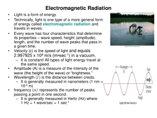
Detection of Electromagnetic Radiation III:Photon Noise Phil Mauskopf, University of Rome 19 January, 2004
Scattering matrix: Ports Ports are just points of access to an optical system. Each port has a characteristic impedance Any optical system can be described completely by specifying all of the ports and their impedances and the complex coefficients that give the coupling between each port and every other port. For an optical system with N ports, there are NxN coefficients necessary to specify the system. This NxN set of coefficients is called the Scattering Matrix
Scattering matrix: S-parameters The components of the scattering matrix are called S-parameters. S11 S12 S13 S14 ... S =
Scattering matrix: Lossless networks - unitarity condition, conservation of energy For a network with no loss, the S-matrix is unitary: SS = I This is just the expression of conservation of energy, For a two port network: 1 + R = T
Scattering matrix: Examples - two-port networks Dielectric interface: S = This is because R = (Z1-Z2)/(Z1+Z2) Going from lower to higher impedance Z1 Z2 gives the opposite sign as going from higher to lower impedance. T R -R T
Scattering matrix: Power divider How about 3-port networks? Can we make an optical element that divides the power of an electromagnetic wave in half into two output ports? Guess: What is the S-matrix for this circuit? What is the optical analogue? 2 Z1 Z1 2 Z1
Scattering matrix: 4-port networks - 90 degree hybrid A (A+iB)/2 (A-iB)/2 B 0 0 1 1 0 0 i -i 1 1 0 0 i -i 0 0 S =
Scattering matrix: 4-port networks - 90 degree hybrid Optical analogue: Half power beam splitter (iA+B)/ 2 A (A+iB)/ 2 B 0 0 1 i 0 0 i 1 1 i 0 0 i 1 0 0 0 0 1 1 0 0 i -i 1 1 0 0 i -i 0 0 0 2 2 0 S = = = With a 90 phase shift on port 2
Scattering matrix: 4-port networks - 180 degree hybrid A (A+B)/ 2 (A-B)/ 2 B 0 0 1 1 0 0 1 -1 1 1 0 0 1 -1 0 0 0 3 3 0 S = = In general lossless scattering matrices SU(n)
Resistive elements in transmission line - loss: R L G C R represents loss along the propagation path can be surface conductivity of waveguide or microstrip lines G represents loss due to finite conductivity between boundaries = 1/R in a uniform medium like a dielectric Z = (R+iL)/(G+iC) Z has real part and imaginary part. Imaginary part gives loss
Resistive elements in transmission line - loss: You can replace loss terms in the scattering matrix (which makes it non-unitary) with additional ports that account for the lost signal. Z=R R L L Z0 Z0 G G C C
Optics: Direct coupling to detectors (simplest) Need to match detector to free space - 377 One way to do it is with resistive absorber - e.g. thin metal film Transmission line model: Converts radiation into heat - detect with thermometer = the famous bolometer! How about other detection techniques? Impedance mismatch? - Non-destructive sampling - sample voltage - high input Z - sample current - low input Z Both cases the signal is reflected 100% E.g. JFET readout of NTD, SQUID readout of TES Z0 + - R=Z0
Optics: Direct coupling to detectors (simplest) Without an antenna connected to a microstrip line, the minimum size of an effective detector absorber is limited by diffraction Single mode - size ~ 2 The number of modes in an optical system is limited by the total throughput: n(modes) = A/2 The throughput is limited by the coupling between optical elements
Two types of mm/submm focal plane architectures: Bare array Antenna coupled IR Filter Filter stack Bolometer array Antennas (e.g. horns) X-misson line SCUBA2 PACS SHARC2 Microstrip Filters Detectors BOLOCAM SCUBA PLANCK
Mm and submm planar antennas: You can have single mode and multi-mode antennas - e.g. scalar feed vs. winston Quasi-optical (require lens): Twin-slot - small number of modes Log periodic - multimode Coupling to waveguide (require horn): Radial probe Bow tie
Optics: Modes and occupation number A mode is defined by its throughput: A = 2 The occupation number of a mode is the number of photons in that mode per unit bandwidth For a single mode source emitting a power, P in a bandwidth , with an emissivity, The occupation number is: N = (P/2h)(1/ ) For a blackbody source at temperature, T, this is just the Bose-Einstein term: N = 1/(exp(h/kT)-1)
Optics: Modes and occupation number N = (P/2h)(1/ ) = 1/(exp(h/kT)-1) Low frequencies (R-J limit): h/kT << 1 N kT/h >> 1 = High photon occupation number Wave noise dominated = Zero point fluctuations High frequencies (Wein limit): h/kT >> 1 N exp(-h/kT) << 1 = Low photon occupation number Shot noise dominated = Johnson-Nyquist noise CMB at millimetre-wavelengths: h/kT ~ 1 so it is in between low and high occupation number!
1990s: SuZIE, SCUBA, NTD/composite 1998: 300 mK NTD SiN PLANCK: 100 mK NTD SiN Shot noise Wave noise
Noise: Formulae The 1 uncertainty in the optical power is: p = h N(1+ N) /( ) N = mode occupation number = efficiency = integration time = central frequency = bandwidth Limits: N >> 1 p = h N/ = Pd/( ) N << 1 p = h N / = Pd h/ /
Noise: Derivation Take an N-port optical system with an NxN scattering matrix, Sij(): Port labels are i = 1…N Incoming wave amplitudes are given by: ai() Outgoing wave amplitudes are given by: bi() Considering only linear systems (for which the S-matrix method applies): bi() = jSij() aj() or b = Sa S = probability amplitude for photon entering port j to exit at port i
Noise: Derivation Start with simplest network - single port = two terminals P Z R Port, P has characteristic impedence = Z = R. Therefore there are no reflections. We can think of this as a transmission line terminated at infinity with another resistor, R
Noise: Derivation Start with simplest network - single port = two terminals P Z Z = R Rp R Where Rp is the port impedence In fact, if you use simulation packages such as ADS, they require that you terminate all ports with a characteristic impedance. If Rp is infinite = open circuit then we have voltage noise If Rp = 0 = short circuit then we have current noise
Noise: Derivation Formula for noise can be derived in (at least) two ways: 1. Brownian motion or random walk of electrons 2. Transmission line model and thermodynamics Both methods give classical solutions that are modified by quantum effects We’ll consider only the transmission line model - from Nyquist Z R1 R2 Based on the principle that in thermal equilibrium there is no average power flow
Noise: Derivation V12 R2/(R1 + R2)2 R1 R2 V22 R1/(R1 + R2)2 If the voltage noise from R1 is given by V1 then the power generated by R1 and dissipated in R2 is given by: V12 R2/(R1 + R2)2 and the power generated by R2 and dissipated in R1 is given by: V22 R1/(R1 + R2)2 Thermodynamics says these must be equal at all frequencies so: Vi2 Ri and Vi2 T. Define power spectrum, SV() = Vi2
Noise: Derivation l Z R R Suppose R1 = R2 = Z Z is a lossless transmission line = L/C Wave velocity in the transmission line v = 1/LC The thermal power delivered to the transmission line from either R1 or R2 in a frequency interval d/2 is: dP = (1/4R) SV() d/2 For a transmission line of length, l the energy stored in the transmission line is equal to the power emitted x travel time = l/v: dE = dP t 2 = (l/2Rv) SV() d/2
Noise: Derivation Z R R If we suddenly cut the lines at the end of the transmission line, a certain amount of energy is trapped in standing waves: dE = dP t 2 = (l/2Rv) SV() d/2 Expanding the standing waves in modes gives: m = (d/2)/(v/2l) Equipartition theorem: average energy per mode = kT dE = mkT = (d l/v)kT = (l/2Rv) SV() d/2 SV() = 4kTR
Noise: Derivation Quantum Mechanics I: Include Bose-Einstein statistics Quantum mechanically, the average thermal energy per mode is given by the energy per photon times the photon occupation number: dE = m nth = (d l/v) /(exp(/kT)-1) Setting this equal to the energy stored in the transmission line: dE = (l/2Rv) SV() d/2 gives, SV() = 4 R/(exp(/kT)-1) = 4 R nth
Noise: Derivation: 4-terminals = 2 ports Impedence representation and S-matrix representation: I1(t) I2(t) b1 b2 Z S V2(t) V1(t) a1 a2 Impedance matrix, Z: Scattering matrix, S: V1 Z11 Z12 I1 b1 S11 S12 a1 V2 Z21 Z22 I2 b2 S21 S22 a2 = = Where ai represents the amplitude of incoming waves and bi represents the amplitude of outgoing waves
Noise: Derivation: 4-terminals = 2 ports Generalize to multiple ports: Obtain noise correlation matrix I1(t) b1 Zij ei Sij i V1(t) a1 I2(t) b2 V2(t) a2 In(t) bn Vn(t) an Sij*() = (1-SS)ij kT Seiej*() = 2(Z+Z)ij kT
Noise: Equations Include Bose-Einstein statistics and obtain the so-called ‘Classical’ formulae for noise correlations: Sij*() = (1-SS)ij kT (1-SS)ij /(exp(/kT)-1) Seiej*() = 2(Z+Z)ij kT 2(Z+Z)ij /(exp(/kT)-1) Relations between voltage current and input/output waves: 1/4Z0 (Vi+Z0Ii) = ai 1/4Z0 (Vi - Z0Ii) = bi or Vi = Z0 (ai + bi) Ii = 1/Z0 (ai - bi)
Noise: Derivation Quantum Mechanics II: Include zero point energy Zero point energy of quantum harmonic oscillator = /2 I.e. on the transmission line, Z at temperature, T=0 there is still energy. Add this energy to the ‘Semiclassical’ noise correlation matrix and we obtain: Seiej*() = 2 (Z+Z)ij coth(/2kT) = 2 R (2nth +1) Sij*() = (1-SS)ij coth(/2kT) = (2nth +1)
Noise: Derivation - Quantum mechanics This is where the Scattering Matrix formulation is more convenient than the impedance method: Replace wave amplitudes, a, b with creation and annihilation operators, a, a, b, b and impose commutation relations: [a, a ] = 1 Normalized so that a a = number of photons [a, a ] = Normalized so that a a = Energy Quantum scattering matrix: b = a + c Since [b, b ] = [a, a ] = then the commutator of the noise source, c is given by: [c, c ] = (I - ||2)
Noise: Quantum Mechanics III: Calculate Quantum Correlation Matrix If we replace the noise operators, c, c that represent loss in the scattering matrix by a set of additional ports that have incoming and outgoing waves, a, b: c i = i a and: (I - ||2)ij= i j Therefore the quantum noise correlation matrix is just: c ici = (I - ||2)ijnth = (I - SS)ijnth So we have lost the zero point energy term again...
Noise: Quantum Mechanics IV: Detection operators An ideal photon counter can be represented quantum mechanically by the photon number operator for outgoing photons on port i: di = b ibi which is related to the photon number operator for incoming photons on port j by: b ibi = (nS*inan)(m Simam) + cici = d Bii() (nS*inan)(m Simam) = n,mS*in Sim anam anam = nth(m,) nm which is the occupation number of incoming photons at port m
Noise: Quantum Mechanics IV: Detection operators Therefore di= mS*imSim nth(m,) + cici = d Bii() Where: cici = (I - SS)iinth The noise is given by the variance in the number of photons: ij2 = di dj - di di = d Bij() ( Bij()+ ij ) Bij() = mS*imSjm nth(m,) + cicj = mS*imSim nth(m,) + (I - SS)ijnth(T,) Assuming that nth(m,) refers to occupation number of incoming waves, am , and nth(T,) refers to occupation number of internal lossy components all at temperature, T
Noise: Example 1 - single mode detector No loss in system, no noise from detectors, only signal/noise is from port 0 = input single mode port: Sim = 0 for i, m 0 S0i = Si0 0 di= d S*i0Si0 nth(0,) + cici = d Bii() ii2 = di dji - di di = d Bii() ( Bii()+ ii ) For lossless system - cici = 0 and ii2 = d Bii() ( Bii()+ ii ) = d Si02 nth() (Si02 nth()+ 1) Recognizing Si02 = as the optical efficiency of the path from the input port 0 to port i we have: ii2 = d nth() (nth()+ 1) express in terms of photon number
Noise: Gain - semiclassical Minimum voltage noise from an amplifier = zero point fluctuation - I.e. attach zero temperature to input: SV() = 2 R coth(/2kT) = 2 R (2nth +1) when nth = 0 then SV() = 2 R Compare to formula in limit of high nth : SV() ~ 4 kTN R where TN Noise temperature Quantum noise = minimum TN= /2k
Noise: Gain Ideal amplifier, two ports, zero signal at input port, gain = G: S11 = 0 no reflection at amplifier input S12 = G gain (amplitude not power) S22 = 0 no reflection at amplifier output S21 = 0 isolated output Signal and noise at output port 2: d2= d S*12S12 nth(1,) + c2c2 = d B22() 222 = d2 d2 - d2 d2 = d B22() ( B22()+ 1 ) c2c2 = (1 - (SS)22)nth(T,) What does T, nth mean inside an amplifier that has gain? Gain ~ Negative resistance (or negative temperature) namp(T,) = -1/ /(exp(-/kT)-1) -1 as T 0
Noise: Gain 0 0 0 G 0 0 G 0 0 0 0 G2 c2c2 = -(1 - (SS)22) = (G2 - 1) d2= d S*12S12 nth(1,) + c2c2 = d B22() 222 = d2 d2 - d2 d2 = d B22() ( B22()+ 1 ) = d (G2 nth (1,)+ G2 - 1)(G2 nth (1,)+ G2) If the power gain is = G2 then we have: 222 = d (nth (1,)+ - 1)(nth (1,)+ ) ~ 2(nth (1,)+ 1)2 for >> 1 and expressed in uncertainty in number of photons In other words, there is an uncertainty of 1 photon per unit SS = =
Noise: Gain 22~ (nth (1,)+ 1) expressed in power referred to amplifier input, multiply by the energy per photon and divide by gain, 22~ h(nth (1,)+ 1) Looks like limit of high nth Amplifier contribution - set nth = 0 22~ h = kTn or Tn = h/k (no factor of 2!)
Noise: Gain What happens to the photon statistics? No gain: Pin = n h and in = h n(1+n) /( ) (S/N)0 = Pin /in = n/(1+n) With gain: Pin = n h and in = h (1+n) /( ) (S/N)G = Pin /in = [n/(1+n)] (S/N)0/(S/N)G = (1+n)/n
Noise: Interferometry What if we want to measure the spectrum of incoming radiation? Two ways: 1. Divide signal into N frequency bands using filters and detect the photons with N detectors 2. Divide signal power by N and detect autocorrelation of the input signal with N lags in N detectors