Designing Logic Circuits: Half Adder, Half Subtractor, and Multiplexer with NAND Gates
This guide covers the design of logic circuits, focusing on the half adder, half subtractor, and multiplexer, using only NAND gates. It begins with the fundamentals of the half adder, explaining its components and operations to produce sum and carry outputs. The half subtractor's functioning is detailed, clarifying how it handles binary subtraction with defined inputs and outputs. Finally, the multiplexer is introduced, emphasizing its role in selecting one of many inputs based on control signals. Understanding these concepts is vital for digital electronics design.


Designing Logic Circuits: Half Adder, Half Subtractor, and Multiplexer with NAND Gates
E N D
Presentation Transcript
LOGIC CIRCUIT Part 2: DESIGN CIRCUIT
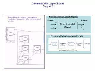
LOGIC CIRCUIT DESIGN x y z F 0 0 0 0 0 0 1 1 0 1 0 0 0 1 1 0 1 0 0 1 1 0 1 1 1 1 0 1 1 1 1 1 Truth Table Boolean Function F = x + y’z x F y Logic Diagram z
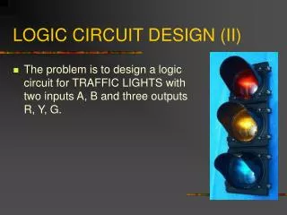
Design Logic Circuit using NAND gates only • E.g. 1: A + B’
Design Logic Circuit using NAND gates only • E.g. 2: A’B + C
Design Logic Circuit using NAND gates only • E.g. 3: [(A + B) . C]’’
Half Adder circuit • To understand what is a half adder you need to know what is an adder first. • Adder circuit is a combinational digital circuit that is used for adding two numbers. A typical adder circuit produces a sum bit (denoted by S) and a carry bit (denoted by C) as the output. • Besides addition, adder circuits can be used for a lot of other applications in digital electronics like address decoding, table index calculation etc. • Adder circuits are of two types: Half adder and Full adder.
Half Adder circuit • Half adder is a combinational arithmetic circuit that adds two numbers and produces a sum bit (S) and carry bit (C) as the output. • The arithmetic operation, addition of two binary digits has four possible elementary operations, namely: • 0 + 0 = 0 • 0 + 1 = 1 • 1 + 0 = 1 • 1 + 1 = 0 with 1 carry • If A and B are the input bits, then sum bit (S) is the X-OR of A and B and the carry bit (C) will be the AND of A and B. • From this it is clear that a half adder circuit can be easily constructed using one X-OR gate and one AND gate.
Half Adder circuit • Inputs: A + B • Outputs: Sum (S) , Carry (C) Boolean Expressions: Sum (S) = A’B + AB’ Carry (C) = AB Logic Circuit Truth Table
Half Subtractor circuit • Half Subtractor is a combinational circuit that performs subtraction of two bits and has two inputs and two outputs. • The two inputs denoted by A and B represents minuend and subtrahend. • The two outputs are the difference “D” and the borrow bit “Bo“.
Half Subtractor circuit • Half Subtractor is a combinational circuit that performs subtraction of two bits and has two inputs and two outputs. • The two inputs denoted by A and B represents minuend and subtrahend. • The two outputs are the difference “D” and the borrow bit “Bo“. Boolean Expressions: Difference (D) = A’B + AB’ Borrow (B0) = A’B Truth Table Logic Circuit
Multiplexer • A multiplexer has many input lines and one output line. • The signal from one input line will be directed to the output line. • The input line is chosen based on the signals which are carried to the multiplexer on another set of input lines called control lines. • Multiplexers are sometimes called selectors because they choose or select one of their inputs. • The number of control lines needed depends on the number of input lines. • A multiplexer with 2 control lines can select from 4 input lines, a multiplexer with 3 control lines can select from 8 input lines. • In general, a multiplexer with n control lines can select from up to 2ninput lines.
Multiplexers • 4-to-1 multiplexer