Digital Logic Circuit
Digital Logic Circuit. Analysis & Design. 王 军. 王晓东. 6.2 TOUNTER. A counter consists of a register and the associated logic. A 4-bit binary counter 74161. CLOCK: synchronous counting input. CLR’ : asynchronous clear (active low). Load’ : synchronous load (active low).


Digital Logic Circuit
E N D
Presentation Transcript
Digital Logic Circuit Analysis & Design 王 军 王晓东
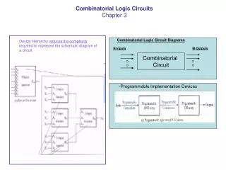
6.2 TOUNTER • A counter consists of a register and the associated logic. A 4-bit binary counter 74161.
CLOCK: synchronous counting input. • CLR’: asynchronous clear (active low). • Load’: synchronous load (active low). • ENT and ENP: count enables (active high). • IND,C,B,A: loading inputs. • OV: overflow output (reaching the maximum-1111)
Note: If the clock is connected to X, it counts to 8; If Y, it counts to 16. • SP3,4b: P471~473 • EX3,4a,5: P481 • LAB14
Experiment 14 A Base-60 Counter Section 1 Introduction and Guidance a. Introduction: Counters may be synchronous or asynchronous and may be base 10 or 16 or else. Most synchronous counters have parallel loads; they may be preset to a value, using the load signal and an input line for each bit. We will have to understand them well and use them skillfully. The purpose of this experiment is to make students master the designing method of a base-60 counter and consolidate the ability of using seven segment displays. b. Guidance: Counters are commercial medium-scale integrated circuits. Design a counter that goes from 0 to 59 and display the count on the two seven segment displays. To implement more complex problems, we definitely choose corresponding chips and gates. Take the following available resources to finish the experiment. Available Resources: 1. SAC-DS4 LOGIC LAB 2. ALTERA MAX+PLUS II 3. TTL chips: 74160, 74138,74373,7448 and 7473
Section 2 Report Fourteen Pre-experiment Find the pin layouts of the chips availed of above. 74160 74373 74138 7448 7473 Draw the circuit diagram of this system which you have designed.
In-experiment Any problem with wiring? Any problem with chips? Any other problems? Testing results in ALTERA MAX+PLUSⅡ(waveform simulations)
Post-experiment Something Learned: