Download
1 / 27
350 likes | 799 Vues
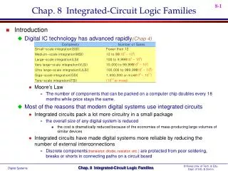
INTEGRATED CIRCUIT LOGIC FAMILY. Introduction. ICs have made digital systems more reliable by reducing the number of external interconnection from one device to another. ICs have reduced the amount of electrical power needed to perform a given function.

E N D
INTEGRATED CIRCUIT LOGIC FAMILY ©2009, CE Department
Introduction • ICs have made digital systems more reliable by reducing the number of external interconnection from one device to another. • ICs have reduced the amount of electrical power needed to perform a given function. • IC cannot handle very large currents or voltages because the heat generated in such small spaces would cause temperature to rise beyond acceptable limits • ICs are principally used to perform low-power circuit operations that are commonly called information processing. ©2009, CE Department
Introduction • Rapidly growth from SSI, with fewer than 12 gates per chip; through MSI, with 12 to 99 equivalent gates per chip • Others – LSI, VLSI, ULSI and GSI • There are some things IC cannot do – when deal with very large current ©2009, CE Department
Digital IC Terminology • VIH (min) – High level input voltage. The minimum level required for a logical 1 at an input. Any voltage below this level will not be accepted as a HIGH by the logic circuit • VIL (max) – The maximum input voltage for logic zero • VOH (min) – The minimum voltage level at a logic circuit output in the logic 1 state under defined load conditions ©2009, CE Department
Digital IC Terminology (cont.) • VOL (max) – Low level output voltage. The maximum voltage level at a logic circuit output in the logical 0 state under defined load conditions • IIH – High level input current. The current that flows into an input when a specified high level voltage is applied to that input • IIL – Low level input current. The current that flows into an input when a specified low level voltage is applied to that input ©2009, CE Department
Digital IC Terminology (cont.) • IOH – High level output current • IOL – Low level output current ©2009, CE Department
Exercise • Describe the input and output logic for IC 7442 ©2009, CE Department
Fan out • Also known as loading factor • Defined as the maximum number of logic inputs that an output can drive reliably • A logic circuit that specify to have 10 fan out can drive 10 logic inputs ©2009, CE Department
Propagation delay • Two types of propagation delay – tPLH , delay time in going from logical 0 to 1; tPHL delay from 1 to 0 ©2009, CE Department
Noise Immunity (cont.) • The high state noise margin VNH is defined as VNH = VOH (min) – VIH (min) • The low state noise margin VNL is defined as VNL = VIL (max) – VOL (max) ©2009, CE Department
Power Requirements • Every IC need a certain power requirement to operate • This power supply is come from the voltage supply that connected to the pin on the chip labeled VCC(TTL) or VDD(MOS) • The amount of power require by ICs is determined by the current that it draws from the VCC • The actual power is ICCxVCC ©2009, CE Department
Cont. • ICC(avg) = (ICCH + ICCL)/2 • PD(avg) = ICC(avg)Xvcc ©2009, CE Department
The TTL Logic Family FIGURE 8-7 (a) Basic TTL NAND gate; (b) diode equivalent for Q1. ©2009, CE Department
TTL NOR gate ©2009, CE Department
TTL Data sheet • In 1964, Texas Instruments corporation introduced the first line of standard TTL ICs • The 54/74 series, most widely used IC logic families • The difference between 54 and 74 series is a range of temperatures • IC number is the same with all series produce by different manufactures • Each manufacturer however usually used the prefix that represent the special words – Texas Instrument uses the prefix SN, National semiconductor uses DM etc ©2009, CE Department
Supply Voltage and Temperature Range • 74ALS series and the 54ALS series use nominal supply voltage (VCC) of 5V, but can tolerate a supply variation of 4.5 to 5.5V. • 74ALS series can operate properly in ambient temperatures ranging from 0 to 70 degrees C, while the 54ALS series can handle -55 to +124 degree C. ©2009, CE Department
Voltage Levels • Input and output voltage levels can be found on the data sheet. • The min and max values shown are for worst case conditions of power supply, temperature and loading conditions
TTL Series Characteristics • We have found the type of ICs – 74, 74LS, 74ALS before • LS – low power Schottky, ALS – advance low power Schottky • The function is same, but the difference is on the characteristic
TTL Series Characteristics • 74 series of TTL – offers a wide variety of gates and flip flops • Consist of: a. Standard TTL, 74 series – no longer be use b. Schottky TTL, 74S series c. Low-power Schottky TTL, 74LS Series d. 74AS e. 74ALS and 74F ©2009, CE Department
Schottky TTL, 74S Series • 7400 series operates using saturated switching in which many of the transistors, when conducting will be in saturated condition • This can causes a storage time delay ts when the transistors switch from ON to OFF and effect the speed • 74S series come to solve the speed problem • It accomplishes this by using a Schottky barrier diode (SBD) ©2009, CE Department
Schottky TTL, 74S Series (cont.) ©2009, CE Department
Advances Schottky TTL, 74AS series • 74AS give more advance on speed switching of TTL ICs at much lower consumption • The comparison is shown in the following table for a NAND gate in each series ©2009, CE Department
Advanced Low Power Schottky TTL, 74ALS Series • Improved on both speed and power dissipation ©2009, CE Department
Example • Use table 8-6 to calculate the dc noise margins for a typical 74LS IC. How does this compare with the standard TTL noise margins ? Solution • 74LS VNH = VOH(min) – VIH(min) = 2.7 – 2.0 = 0.7 V ©2009, CE Department
TTL Loading and Fan Out ©2009, CE Department