Download

1 / 46
480 likes | 595 Vues
Discover the specifications of various logic IC types focusing on fan-in, fan-out, input, and output characteristics. Learn about TTL and CMOS families, power requirements, voltage ranges, unconnected inputs, digital IC terminology, fan-out, and propagation delays.

E N D
Integrated Circuit Logic Families
Objective • Describe the specification of the various logic ICs with emphasis on fan-in, fan-out, input and output characteristic. • Verify the common technical specification of TTL and CMOS logic families.
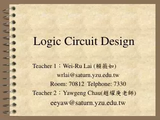
1. Basic Characteristics • Digital ICs are a collection of resistors, diodes, and transistors fabricated on apiece of semiconductor material (usually silicon). • Digital ICs are categorized according to their circuit complexity as measured by the number of equivalent logic gates packaged within. • ComplexityNumbers of gates • Small-scale integration (SSI) Fewer than 12 • Medium-scale integration (MSI) 12 to 99 • Large-scale integration (LSI) 100 to 9999 • Very large-scale integration (VLSI) 10,000 or more • Ultra large-scale integration (ULSI) 100,000 or more
2. Types of IC families: 2.1 TTL Family TTL Prefix Example IC • Standard TTL 74 7404(hex inverter) • High speed TTL 74H 74H04 • Low power TTL 74L 74L04 • Low power Schottky TTL 74LS 74LS04 • Advanced Schottky 74AS 74AS04 • Advanced low power Schottky TTL 74ALS 74ALS04
2.2 CMOS Family CMOS Prefix Example IC • Metal oxide 40 or 140 4001 or 14001 • CMOS (quad NOR gates) • Metal oxide, pin compatible 74C 74C02 • with TTL (quad NOR gates) • Silicon gate, pin compatible 74HC 74HC02 • with TTL, high speed (quad NOR gates) • Silicon gate, high speed, 74HCT 74HCT02 • electrically compatible with TTL (quad NOR gates)
2.3 Power and Ground • Digital ICs are DC powered with ground. • Power supply pin for TTL circuit is labeled Vcc and for CMOS circuit is labeled Vdd.
3. Logic-level Voltage Ranges Logic 1 Logic 1 5V 5V Indeterminate 3.5V Indeterminate 2V Logic 0 1.5V Logic 0 0.8V 0V 0V TTL CMOS
4. Unconnected (Floating) Inputs A A A X = AB X = AB X = AB B B B • 4.1 A floating TTL input acts as logic 1 • Inputs not used should be connected to logic HIGH as a floating TTL input is extremely susceptible to picking up noise signals that can adversely affect the device’s operation. • A floating TTL input will measure a DC level between 1.4V to 1.8V. Unconnected (floating) (a) (b) (c) Fig 5.1 Three ways to handle unused logic inputs
If a CMOS input is left floating, it may become overheated and eventually destroyed itself. • Thus, all inputs to a CMOS IC must be connected to a LOW or a HIGH level or to the output of another IC. • A floating CMOS input will not measure as a specific DC voltage but fluctuate randomly as it picks up noise. • Thus, it does not act as a logic 1 or logic 0 and its effect on the output is unpredictable.
5. Digital IC terminology • 5.1 Voltage parameters • VIH (min) – High-Level Input Voltage • The voltage level required for logic 1 at an input. • Any voltage below this level will not be accepted as a HIGH by the logic circuit. • VIL (max) – Low-Level Input Voltage • The voltage level required for logic 0 at an input. • Any voltage above this level will not be accepted as a LOW by the logic circuit. • VOH (min) – High-Level Output Voltage • The voltage level at a logic circuit output in the logic 1 state. • The maximum value of VOH is usually specified. • VOL (max) – Low-Level Output Voltage • The voltage level at a logic circuit output in the logic 0 state • The maximum value of VOL is usually specified.
5.2 Current parameters • IIH – High-Level Input Current • The current the flows into an input when a specified HIGH-level voltage is applied to that input. • IIL – Low-Level Input Current • The current that flows into an input when a specified LOW-level voltage is applied to that input. • IOH – High-Level Output Current • The current that flows from an output in the logical 1 state under specified load conditions. • IOL – Low-Level Output Current • The current that flows from an output in the logical 0 state under specified load conditions.
IOH IIH IOL IIL + + + VOH VOL VIL _ _ _ + VIH _ HIGH LOW Current and Voltages in the 2 logic inputs
6. Fan-Out • A logic circuit output is specified to drive a certain fixed number of logic inputs. • The fan-out (also called loading factor) is defined as the maximum number of standard logic inputs that an output can drive reliably. • For example, a logic gate specified to have a fan-out of 10 can drive 10 standard logic inputs. If this number is exceeded, the output logic level voltages cannot be guaranteed.
7. Propagation Delays • A logic signal always experiences a delay in going through a circuit. • Two propagation delay times are defined as: • tPLH – delay time in going from logical 0 to logical 1 state. • tPHL – delay time in going from logical 1 to logical 0 state. • In general, tPHL and tPLH are not the same value, and both will vary depending on loading conditions. The values of propagation times are used as a measure of the relative speed of logic circuits. For example, a logic circuit with values of 10ns is a faster logic circuit than one with values of 20ns.
8. Noise Immunity • The noise immunity of a logic circuit refers to the circuit’s ability to tolerate noise voltages on its inputs. • A quantitative measure of noise immunity is called noise margin.
Logic 1 Logic 1 { Disallowed range VNH Indeterminate range VNL { Logic 0 Logic 0 (a) (b) VOH (min) VIH (min) Voltage VIL (max) VOL (max) Output voltage ranges Input voltage requirements • Diagram showing range of voltages that can occur at a logic circuit output • Input voltage requirements at a logic circuit input
8.1 DC Noise Margins • The high-state noise margin VNH is defined as • VNH = VOH(min) – VIH(min) • The low-state noise margin VNL is defined as • VNL = VIL(max) – VOL(max)
9. Current-Sourcing and Current-Sinking Logic LOW LOW IIH • 9.1 Current-sourcing action • Driving gate supplies (sources) current to load gate in HIGH state. +VCC Load gate Current sourcing Driving gate supplies (sources) current to load gate in HIGH state. VOH Driving gate Fig 5.2 (a) Current Sourcing Action
IIL HIGH HIGH • 9.2 Current-sinking action • Driving gate receives (sink) current from load gate in LOW state. +VCC Driving gate Current sinking Driving gate receives (sinks) current from load gate in LOW state. VOL Load gate Fig 5.2 (b) Current Sinking Action
10. Standard TTL series characteristics Noise Margins (worst case) VNL = VNH = 400mV Average power dissipation Pd = 10mW Average propagation delay td = 9nsec Typical fan-out = 10 Standard 74 series voltage levels Minimum Typical Maximum VOL - 0.1 0.4 VOH 2.4 3.4 - VIL - - 0.8 VIH 2.0 - -
10.1 Other TTL series • Low-Power TTL, 74L series • Same basic circuit as standard 74 series except that all resistor values are increased, thus reducing the power requirements. • Increased resistor values results in longer propagation delays. • Suitable for low frequency operation. • Has become obsolete. • High-Speed TTL, 74H series • Smaller resistor values used and have much faster switching speed with an average propagation delay of 6ns. • The power dissipation, however, is higher.
Schottky TTL, 74S series • A Schottky Barrier Diode (SBD) is included to increase switching speed. Schottky diode • 74S have twice the speed of 74H at about the same power requirement.
Low-Power Schottky TTL, 74LS series (LS-TTL) • Lower-powered, slower speed version of the 74S series. • Most common series in TTL family. • e) Advanced Schottky TTL, 74AS series (AS TTL) • Improved in speed over the 74S series at a much lower power requirement. • Fastest TTL series and speed power product is lower than 74S series. • Requires lower input current (IIL, IIH) that results in a greater fan-out. • f) Advanced Low-Power Schottky TTL, 74ALS series • Lowest speed-power product of all the TTL series. • Lowest gate power dissipation. • Higher fan-out.
11. TTL loading and fan-out +5V 1 IOL 1 +5V VOL IIL IIL Fig 5.3 (a) • Fig 5.3 (a) shows a standard TTL output in the LOW state connected to drive several standard TTL inputs. • With gate 1 output in the LOW state, it will sink an amount of current IOL which is the sum of the IIL currents from each input.
16mA [IOL (max)] = = 10 1.6mA [IIL (max)] • Example: In the 74 series IC, IIL = 1.6mA for each input, VOL(max) = 0.4V and VIL(max) = 0.8V • Assuming gate 1 output can sink up to 16mA before its output voltage reaches VOL(max), the number of loads that can be connected to its output will be • If more than 10 loads are connected at gate 1 output, its IOL will increase and causes VOL to increase above 0.4V which is usually undesirable. • This will reduce the noise margin at the IC inputs, since • VNL = VIL(max) – VOL(max)
IOH 0 0 IIH IIH VOH • Fig 5.3 (b) shows the TTL output in the HIGH state. +5V Fig 5.3 (b) • Gate 1 output acts as a current source supplying a total current IOH that is the sum of the IIH currents of each TTL input. • If too many loads are being driven, IOH will increase thereby bringing VOH below VOH(min). This will in turn reduce the HIGH state noise margin and could cause VOH to go into the indeterminate range.
11.1 Determining the Fan-out • To determine how many different inputs an IC output can drive, one needs to know the current drive capability of the output [i.e. IOL(max) and IOH(max)] and the current requirements of each input (i.e. IIL and IIH).
Exercise: • How many 7400 NAND gate inputs can be driven by a 7400 NAND gate output? • Given: IOL(max) = 16mA • IIL(max) = 1.6mA • IOH(max) = 0.4mA • IIH(max) = 40uA • How many 74ALS20 NAND gates can be driven by the output of another 74ALS20? • Given: IOH(max) = 0.4mA • IOL(max) = 8mA • IIH(max) = 20uA • IIL(max) = 0.1mA
1.6mA in the LOW state 1 unit load (UL) = 40uA in the HIGH state • 11.2 Unit Loads • The device input and output currents is specified in terms of UNIT LOAD (UL). • Example: If an IC has a fan-out of 10 UL, it means • IOH(max) = 10 x 40uA = 100uA • IOL(max) = 10 x 1.6mA = 16mA
Exercise: • The output of a 7404 inverter is providing the clock signal to a parallel register made up of 74107 J K FFs. • What is the maximum number of FFs that this clock signal can drive? • Given: 7404’s fan-out = 20 UL (HIGH) and 10 UL (LOW) • 74107’s clock pulse input requirements = 2 UL in both states.
12. MOS Digital Integrated Circuits • The transistors of MOS technology are field-effect transistors called MOSFETs. • The advantages of MOSFET are that it is: • Relatively simple and inexpensive to fabricate (since no other components needed) • Small • Consuming lesser power • MOS ICs can accommodate a much larger number of circuit elements on a single chip than a bipolar ICs. • This higher packing density of MOS ICs result in greater system operating speed due to the reduction of external connections. • However, MOS ICs are relatively slow in operating speed as compared to bipolar ICs.
12.1 Digital MOSFET circuits • Three categories of MOSFETs: • 1. P-MOS :- P-channel enhancement MOSFETs • 2. N-MOS :- N-channel enhancement MOSFETs • 3. C-MOS :- Complementary MOS • P-MOS and NMOS digital ICs have a greater packing density and more economical as compared to CMOS ICs. • N-MOS is twice as fast as P-MOS. • CMOS has greater complexity and lowest packing density of the MOS families. • CMOS has higher speed and much lower power dissipation among the MOS families.
12.2 Characteristics of MOS logic • MOS logic families compared to bipolar logic families: • a) Slower speed • b) Requires much less power (large resistance) • c) Better noise margin • d) Greater supply voltage range • e) Higher fan-out • f) Simplest to fabricate (only N-MOS or P-MOS elements are used)
12.3 CMOS series characteristics • 4000 series • 2 versions, namely 4000A and 4000B with the “B” series having higher output current capabilities. • 74C series • pin-for-pin and function-for-function compatible with TTL devices having the same number. • 74HC series (high speed CMOS) • higher switching speed and higher output current capability. • 74HCT series • voltage-compatible with TTL devices. • can be driven directly by a TTL output.
12.4 Voltage levels • When CMOS outputs drive only CMOS inputs, the output voltage levels will be very close to 0V for the LOW state, and +Vdd for the HIGH state. • This is due to very high CMOS input resistance drawing very little current from the CMOS output that is driving it. • The input voltage requirements for both logic states are expressed as a percentage of the supply voltage as such: • VIL(max) = 30% of Vdd • VIH(min) = 70% of Vdd • For example, when a CMOS is operating from Vdd = +5V, it will accept any input voltage less than VIL(max) = 1.5V as a LOW, and any input voltage greater than VIH(min) = 3.5V as a HIGH.
12.5 Noise Margins • CMOS noise margins are determined as follows: • VNH = VOH(min) – VIH(min) • = Vdd – 70% Vdd • = 30% Vdd • VNL = VIL(max) – VOL(max) • = 30% Vdd – 0 • = 30% Vdd • The noise margins are the same in both states and depend on Vdd. • For example, at Vdd = +5V, the noise margins are both 1.5V which is better than TTL. • This makes CMOS attractive for applications that are exposed to a high-noise environment.
12.6 Power dissipation • When CMOS logic circuit is in static state (not changing), its power dissipation, Pd, is extremely Low. • However, the power dissipation will increase in proportion to frequency at which the circuits are switching states. • Each time a CMOS output switches from ‘0’ to ‘1’, a transient charging current has to be supplied to the load capacitance which consists of the combined input capacitances of any loads being driven and the device’s own output capacitance. • These narrow spikes of current are supplied by Vdd, which can be of 5mA. As the switching frequency increases, there will be more of these current spikes and the average current drawn from Vdd will increase. • Thus, at higher frequencies, CMOS begins to lose some of its advantage over other logic families.
5V VIN ID 0V 5V VOUT + 0V VIN ID _ 0V +5V ON P VOUT CLOAD N OFF Fig 5.4 Current spikes drawn from Vdd each time the output switches from ‘0’ to ‘1’
12.7 Fan-out • CMOS inputs have extremely large resistance (10M ohms) that draws essentially no current from the signal source. • Each CMOS inputs has a capacitance (5pF) that limit the number of CMOS inputs that one CMOS output can drive. • The CMOS output has to change and discharge the parallel combination of each input number of loads being driven. • Typically, each CMOS load increases the driving circuit’s propagation delay by 3nsec. • CMOS outputs are limited to a fan-out of 50 for low frequency operation. • For higher frequency, the fan-out would have to be less.
Gate 1 output drives a total CLOAD of N x 5pF To other loads Fig 5.5 Each CMOS input adds to the total load capacitance seen by the the driving gate’s output
12.8 Unused inputs • CMOS input should never be left disconnected. • All CMOS inputs have to be tied either to a fixed voltage level (0V or Vdd) or to another input. • An unconnected CMOS input is susceptible to noise and static charges that could easily bias the P and N-channel MOSFETs in the conductive state, resulting increased power dissipation and possible overheating.
Questions: • When a TTL logic output goes Low, current will flow from the supply through the load to the TTL ground. This process is known as • a) fan-in. • b) fan-out. • c) current sinking. • d) current sourcing. • Applying 2.4V to a CMOS input with a 10V power supply is interpreted by the IC as • a) a HIGH logic level. • b) a LOW logic level. • c) a prohibited logic level. • d) an undefined logic level.
Table 1 Output Drive Input Loading LS-TTL IOH = 400uA IOH = 8mA IIH = 20uA IIL = 400uA • Refer to Table 1. The calculated fan-out when interfacing LS-TTL to LS-TTL is • a) 1. • b) 10. • c) 20. • d) 400. • The number of gate inputs a logic gate can drive is called • a) fan out. • b) noise immunity. • c) propagation delay. • d) power dissipation.
The HIGH logic level of a TTL must be within • a) +1V to 1.5V. • b) +1.5V to 1.9V. • c) +25V to 4.9V. • d) above +5V. • In a logic circuit, the maximum number of standard logic inputs that an output can drive reliably is called • a) fan in. • b) fan out. • c) unit load. • d) gain factor.
The indeterminate range of a CMOS IC with a VDD of +5V lies between • a) 1V and 3V. • b) 1.5V and 3.5V. • c) 2V and 4v. • d) 2.5V and 3.5V. • Any input of a TT circuit that is left disconnected will • a) behave like a logical 0. • b) behave like a logical 1. • c) oscillate between logic 0 and logic 1. • d) be transparent to the rest of the circuit.