Download
1 / 2
20 likes | 188 Vues
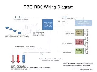
WhisperGreen Select Wiring Configurations. 3) Basic Wiring Diagram (ON/OFF for Single Speed) Signal Wires must be capped separately No Modules will function when fan is switched off. 1) Manual Control Wiring Diagram (ON/OFF or Boost from Low Speed to High Speed)

E N D
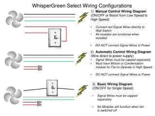
WhisperGreen Select Wiring Configurations 3) Basic Wiring Diagram (ON/OFF for Single Speed) • Signal Wires must be capped separately • No Modules will function when fan is switched off 1) Manual Control Wiring Diagram (ON/OFF or Boost from Low Speed to High Speed) • Connect red Signal Wires directly to Wall Switch • All modules are functional when installed • DO NOT connect Signal Wires to Power 2) Automatic Control Wiring Diagram (Wire direct to power supply) • Signal Wires must be capped separately • Must have Motion or Condensation module for Fan to Operate in High Speed • DO NOT connect Signal Wires to Power
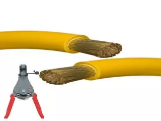
WIRING METHOD 3 – For On/Off Operation Only (No plug in modules) Fan Power NOTE: This wiring method may cause Plug & Play modules to not function correctly. Red wires must be capped separately WIRING METHOD 2 – For AUTOMATIC CONTROL only (All Plug & Play Modules) Fan Power NOTE: This wiring method is for AUTOMATIC CONTROL of the fan (motion sensor/humidity control ONLY). No manual control. Red wires must be capped separately. WIRING METHOD 1 – For MANUAL CONTROL & All Plug & Play modules Fan Power NOTE: This wiring method for MANUAL CONTROL of the fan. Red wires loop to Single Pole switch.