Understanding Electric and Magnetic Fields: Properties and Applications
This article delves into the fundamental principles of electric and magnetic fields, exploring key concepts like electric charge properties, Coulomb's Law, and Gauss's Law. It explains how opposite charges attract while like charges repel, and outlines the quantization and conservation of charges in isolated systems. The relationship between electric potential, capacitance, and resistance is also covered, along with Kirchhoff's rules in circuit analysis. Finally, the behavior of charged particles in magnetic fields and their trajectories are discussed.

Understanding Electric and Magnetic Fields: Properties and Applications
E N D
Presentation Transcript
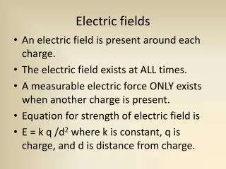
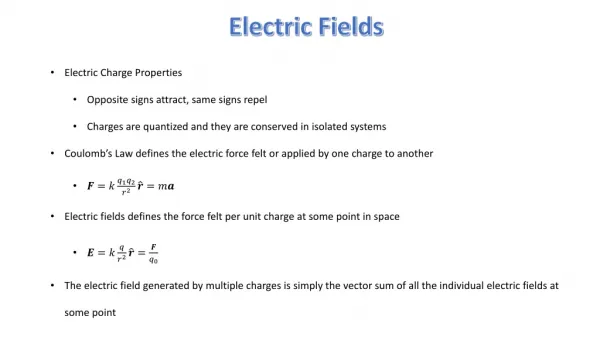
Electric Fields • Electric Charge Properties • Opposite signs attract, same signs repel • Charges are quantized and they are conserved in isolated systems • Coulomb’s Law defines the electric force felt or applied by one charge to another • Electric fields defines the force felt per unit charge at some point in space • The electric field generated by multiple charges is simply the vector sum of all the individual electric fields at some point
Electric Fields • The total electric field at point P is going to be the sum of the two electric fields • Since electric fields are vectors we need to use vector decomposition to find the x component of the electric field and y component of the electric field • The electric field vector of • The electric field vector of
Electric Fields • The net electric field in the x direction • The net electric field in the ydirection
Gauss’s Law • Electric Flux is defined as number of electric field lines that pass through a given surface • The angle is the angle between the area vector (which will be normal to the surface of the area) and the electric field vector • Gauss’s Law says that the net electric flux through any closed GaussianSurface is equal to the net change inside divided by • The electric field inside a conductor is zero. All the charges are located on the surface of the conductor.
Gauss’s Law • Because of the symmetry of the electric field we can use Gauss’s Law to find the electric field at some point r • From the image we can see that a cylindrical Gaussian Surface will be the best choice. • This is because the angle between the area vector and electric field vectors is zero • Applying Gauss’s Law
Gauss’s Law • is given by λ multiplied by the length of our Gaussian Surface • Lastly the coulomb constant (k) can be introduced
Electric Potential • Moving a positive charge through an electric field changes the charge-field system’s potential energy • The electric potential or voltage of a system is defined as the change in potential energy per unit charge • Note that voltage is a scalar value not a vector • Based off the above definition we can also define the electric field as the negative derivative of the voltage • Similar to electric fields the net voltage as some point in space can be found by summing together all the individual voltages together
Electric Potential • Since voltage is a scalar value, no vector decomposition is needed. Thus we just add the two voltages together
Capacitance • A capacitor is made of two conducting plates that store charges when a voltage is applied. • The capacitance of any capacitor is given by the following equation: • Capacitance only depends on the geometry of the capacitor • In series the equivalent capacitance is given by: • In parallel the equivalent capacitance is given by:
Capacitance • When ever we are asked to find the equivalent capacitance of a system, we essentially want to combine all the individual capacitors into a single one • The junction after goes to both . Because of this we can say that are in parallel and that their equivalent resistance is in series with • parallel • in series with
Current and Resistance • Current is defined as the amount of charge that passes through a cross sectional area in some time interval • Resistance is the inverse of the conductivity of a conduct and is a geometric value: • Ohm’s Law relates the potential difference across a conductor to its resistance and how much current is passing through • If there is a potential difference across a given element than energy is being delivered to said element. The rate at which the energy is given is the power:
Current and Resistance • An electromotive force or emf is voltage across the battery • The equivalent resistance of resistors in series is given by: • The equivalent resistance of resistors in parallel is given by: • Kirchhoff’s Rules • Junction Rule: at any junction, the sum of the currents must equal to zero • Loop Rule: The sum of the potential differences across all electric elements around any circuit loop is zero.
Current and Resistance • Since the resistors are in parallel the equivalent resistance is given by: • In parallel the voltage across each resistor will be the same. Thus Ohm’s Law can be used to find the current • Since we know the current across each resistor we can easily find the power delivered to each resistor
Magnetic Fields • If a charged particle travels with some velocity through an external magnetic field is will experience a magnetic force given by the following equation: • Or if a wire carrying a current is placed in a magnetic field • Magnetic forces do not do any work on moving particles • However, magnetic forces can change the trajectory of the particles path
Magnetic Fields A proton is moving in a circular orbit of radius 0.14 meters in a uniform 0.35-T magnetic field perpendicular to the velocity of the proton. Find the speed of the proton. • The magnitude of the magnetic force felt by the proton • In this case the magnetic force is causing the centripetal force • Solving for velocity:
Sources of Magnetic Fields • The Biot-Savart law says that the magnetic field at some point in space is due to length element that carries a steady current • Ampere’s Law says that the line integral of the magnetic field around any closed path ( in this case this closed path is called an Amperian Loop) is equal to the total steady current through the closed path • Both of these law show that there is a relationship between currents and magnetic fields • Gauss’s Law of magnetism: • The magnetic field equations for both a toroid and solenoid
Sources of Magnetic Fields A long, straight wire of radius R carries a steady current I that is uniformly distributed through the cross section of the wire. Calculate the magnetic field at a distance r from the center of the wire in both
Sources of Magnetic Fields • Ampere’s Law
Faraday’s Law • Magnetic Flux is defined as the “amount” of magnetic field passing though an area: • Faraday’s Law of induction states that the emf induced in a loop is directly proportional to the time rate of change of magnetic flux through the loop: • Or in its general form • Len’s Law states that the induced current and induced emf occurs in the opposite direction as to create a magnetic field which opposes the one that produced them
Faraday’s Law • The conducting bar moves on two frictionless, parallel rails in the presence of a uniform magnetic field directed into the page. The bar has a mass m, and its length is l. The bar is given an initial velocity v to the right and is released at t=0. • Part A: Find the velocity of the bar as a function of time. • Part B: Show that the same result is found by using an energy approach.
Faraday’s Law • As the bar moves there is a change in the magnetic flux • Faraday’s Law • Newton’s Law to find velocity
Inductance • When a current is a loop of wire changes with time an emf will be produced as a result of Faraday’s Law • This is because a current that is changing in time will cause the magnetic flux to change in time • Inductance is a measurement of how much opposition the loop offers to a change in the current of the loop. • Similar to capacitance its value is based upon the geometry of the inductor • The inductance of a solenoid: • Mutual Inductance allows us to relate the induced emf in a coil to the changing source current in a nearby coil:
Inductance • Consider a uniformly wound solenoid having N turns and a length L. Assume L is much longer than the radius of the windings and the core of the solenoid is air. • Part A: Find the inductance of the solenoid • **Remember inductance is the L value**
Inductance • Before the current is turned on there is no magnetic field in the solenoid. But when the current is turned a magnetic field will be created over some time interval • A changing magnetic field means there is a changing magnetic flux • Since there are N turns we have • From Faraday’s Law • Thus the inductance of the system is:
Alternating Current • RMS Current and Voltage • If an AC circuit consists of only a resistor and a source, then the current is in phase with the voltage • If an AC circuit consists of only a inductor and a source, then the current lags the voltage • If an AC circuit consists of a capacitor and a source, then the current leads the voltage
Alternating Current • The Impedance of an RLC Circuit: • The angle between the applied voltage vector and current is called the phase angle: • The RMS Current for RLC Circuit: • Power of an AC Circuit • The maximum rms current value occurs at the resonance frequency. This is the frequency at which
Alternating Current • A: Find the inductive reactance, capacitive reactance, and the impedance. • B: Find the maximum current in the circuit. • C: Find the phase angle between the current and voltage. • D: Find the maximum voltage across each element.
Alternating Current • Find the inductive reactance, capacitive reactance, and the impedance. • Find angular frequency • Find inductive reactance • Find inductive capacitance • Find impedance
Alternating Current • Find the maximum current in the circuit • Find the phase angle between the current and voltage • Find the maximum voltage across each element
Electromagnetic Waves • Lorentz Force describes the force felt by a charged particle in the presence of both an electric and magnetic field: • Maxwell’s Equations • Electromagnetic waves are predicted by Maxwell’s equations. • Speed of Light
Electromagnetic Waves • The relationship between the frequency and the wavelength of an electromagnetic wave: • The electric field and magnetic field are perpendicular to each other as well as the direction of propagation • The instantaneous magnitudes of E and B is given by the following equation: • Electromagnetic waves carry both energy and momentum • The Poynting vector represents the rate at which energy passes through a unit area by electromagnetic radiation ( in other words the power per unit area) • Wave Intensity
Electromagnetic Waves • Start with the relationship between frequency and wavelength: • Use the relationship between frequency and period:
Electromagnetic Waves • To find the magnitude use the relationship between E and B: • c • Since the wave is traveling in the x direction and the electric field is in the y direction, the magnetic field must be in the z direction. This is because the fields are perpendicular to each other as well as the direction of propagation.