Electric Fields
This guide delves into electric fields and electrostatic phenomena, focusing on Coulomb’s Law and the forces between static charges. Learn about the concept of electric fields defined in terms of the force on a test charge, how to represent these fields with electric field lines, and their behavior in various scenarios. We explore the equilibrium positions of charged objects, the superposition principle, and vector addition of forces. Additionally, we provide examples and calculations illustrating electric dipoles and field strength in a system of point charges.


Electric Fields
E N D
Presentation Transcript
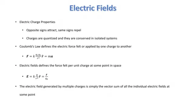
Electrostatic Phenomena Coulomb’s Law: force between static charges r 1 q q Ftotal F2 F1 = ˆ 1 2 F r 12 12 pe 2 4 r 12 o Superposition q1 Ftotal = F1+ F2 + ... Remember: vectors add by components! Q q2 Last Time…
Define Electric Field in terms of force on a test charge How to think about fields Electric Field Lines Example Calculation: Electric Dipoles Today...
Lecture 2, Act 1 Two balls of equal mass are suspended from the ceiling with nonconducting wire. One ball is given a charge +3q and the other is given a charge +q. +q +3q +3q +q (a) (b) g +3q +q Which of the following best represents the equilibrium positions? +3q +q (c)
Lecture 2, Act 1 +q +3q +q +3q +q (a) (b) (c) The force on the +3q charge due to the +qcharge must be equal and opposite to the force of the +3q charge on the +qcharge Amount of charge on each ball determines the magnitude of the force, but each ball experiences the same magnitude of force Symmetry, therefore, demands (c) P.S. Knowing the form of Coulomb’s law you can write two equations with two unknowns (T andq) Which best represents the equilibrium position? +3q Remember Newton’s Third Law!
Preflight 2: +10 μC +1 μC a) b) c) Two charges q = + 1 μC and Q = +10 μC are placed near each other as shown in the figure. 6) Which of the following diagrams best describes the forces acting on the charges:
The Electric Field A simple, yet profound observation - The net Coulomb force on a given charge is always proportional to the strength of that charge. = F F1 + F2 F1 F æ ö r ˆ ˆ Q q r q r ç ÷ = + 1 1 2 2 F ç ÷ pe 2 2 4 r r è ø 0 1 2 F2 - Wecan now define a quantity, the electric field, which is independent of the test charge, Q, and depends only on position in space: r r F The qiare the sources of the electric field º E Q q1 Q q2 test charge
The Electric Field r r F º E Q Collection of Point Charges Charge Distribution F = Q E + + - + + + - Test charge Q + + + - + + + - + + + + + + + “Net” E at origin - These charges or this charge distribution are the “source” of the electric field throughout space With this concept, we can “map” the electric field anywhere in space produced by any arbitrary:
Example: Electric Field What is the electric field at the origin due to this set of charges? y 1) Notice that the fields from the top-right and bottom left cancel at the origin? a a +q +q 2) The electric field, then, is just the field from the top -left charge. It points away from the top-left charge as shown. 3) Magnitude of E-field at the origin is: a a Q x a +q kq = E 2a2 kq cosq = Ex 2a2 kq - sinq = Ey kq 1 2a2 = 2a2 2 kq 1 - = 2a2 2 The x and y components of the field at (0,0) are:
Example: Electric Field y a a q 1 +q = +q k E x 2 2 a 2 a a x Q a +q If the test charge Q is positive, the force will be in the direction of the electric field If the test charge Q is negative, the force will be against the direction of the electric field F is F is Now, a charge, Q, is placed at the origin. What is the net force on that charge?
Let’s Try Some Numbers... If q = 5 mC, a = 5 cm, and Q = 15 mC. y Then Ex= 6.364 106 N/C and Ey= -6.364 106 N/C a a +q +q a a x Fx = QEx and Fy = QEy a Fx=95.5 N Fy=-95.5 N So... +q and We also know that the magnitude of E = 9.00 106 N/C We can, therefore, calculate the magnitude of F F = |Q| E = 135N
Lecture 2, Act 2 y E q1 d q2 x Two charges, q1 and q2, fixed along the x-axis as shown produce an electric field, E, at a point (x,y)=(0,d)which is directed along the negative y-axis. - Which of the following is true? (a) Both chargesq1 and q2are positive (b) Both chargesq1andq2are negative (c) The chargesq1andq2have opposite signs
Lecture 2, Act 2 y E q1 d q2 x E E E q1 q1 q2 q2 q1 q2 (a) (b) (c) Two charges, q1 and q2, fixed along the x-axis as shown produce an electric field, E, at a point (x,y)=(0,d)which is directed along the negative y-axis. - Which of the following is true? (a) Both chargesq1 and q2are positive (b) Both chargesq1andq2are negative (c) The chargesq1andq2have opposite signs
Reality of Electric Fields • The electric field has been introduced as a mathematical convenience, just as the gravitational field of Physics 111 There is MUCH MORE to electric fields than this! IMPORTANT FEATURE:E field propagates at speed of light • NO instantaneous action at a distance (we will explain this when we discuss electromagnetic waves) • i.e., as charge moves, resultant E-field at time tdepends upon where charge was at timet - dt For now, we avoid these complications by restricting ourselves to situations in which the source of the E-field is at rest. (electrostatics)
Ways to Visualize the E Field vector map field lines + chg + chg + + Consider the E-field of a positive point charge at the origin
Rules for Vector Maps + chg + Direction of arrows indicates the direction of the field at each point in space Length of arrows is proportional to themagnitude of the field at each point in space
Rules for Field Lines - + Field at two white dots differs by a factor of 4 sincer differs by a factor of 2 (Coulomb’s law, E ~1/ r2) Local density of field lines / unit area also differs by a factor of 4 in 3D: same # lines spread over area ~ r2 graphical “trick”for visualizingE fields Lines leave (+) charges and return to (-) charges Number of lines leaving/entering chargeµamount of charge Field lines never cross → Tangent of line = direction ofE at each point → Local density of field lines ~magnitude ofE at each point
Preflight 2: 6) A negative charge is placed in a region of electric field as shown in the picture. Which way does it move ? a) up c) left e) it doesn't move b) down d) right
7) Compare the field strengths at points A and B. a) EA > EB b) EA = EB c) EA < EB
Lecture 2, Act 3 y 2a +Q a a x a -Q (b) Ex(2a,a) = 0 (c) Ex(2a,a) > 0 (a) Ex(2a,a) < 0 • Consider a dipole (2 separated equal and opposite charges) with the y-axis as shown. • Which of the following statements aboutEx(2a,a)is true?
Lecture 2, Act 3 y 2a +Q a a x a -Q (b) Ex(2a,a) = 0 (c) Ex(2a,a) > 0 (a) Ex(2a,a) < 0 Solution: Draw some field lines according to our rules. Ex www.falstad.com Falstad's Electrostatics Applets: 2D Falstad's Electrostatics Applets: 3D • Consider a dipole (2 separated equal and opposite charges) with the y-axis as shown. • Which of the following statements aboutEx(2a,a)is true?
Preflight 2: 3) What is the direction of the electric field at point A? a) up b) down c) left d) right e) zero 4) What is the direction of the electric field at point B? a) up b) down c) left d) right e) zero Two equal, but opposite charges are placed on the x axis. The positive charge is placed at x = -5 m and the negative charge is placed at x = +5m as shown in the figure above.
Field Lines From Two Opposite Charges Dipole Dipoles are central to our existence!
The Electric Dipole y +q a x q a E E r -q Ex = ?? Ey = ?? Symmetry Ex(x,0) = 0 see the appendix for further information What is the E-field generated by this arrangement of charges? Calculate for a point along x-axis: (x, 0)
Electric Dipole Field Lines What can we observe about E? Ex(x,0) = 0 Ex(0,y) = 0 We derived: ... for r >> a, Lines leave positive chargeand return to negative charge Field largest in space between two charges
Field Lines From Two Like Charges 4 • There is a zero halfway between the two charges • r >> a: looks like the field of point charge (+2q) at origin
y + + + + + + + + + R + + + + x + + + + + + + + + Lecture 2, ACT 4 Consider a circular ring with total charge +q. The charge is spread uniformly around the ring, as shown, so there is λ = q/2pR charge per unit length. The electric field at the origin is (b) (a) zero (c)
y + + + + + + + + + R + + + + x + + + + + + + + + The key thing to remember here is that the total field at the origin is given by the vector sum of the contributions from all bits of charge. If the total field were given by the algebraic sum, then (b) would be correct (give it a try) … but we’re dealing with vectors here, not scalars! Note that the E field at the origin produced by one bit of charge is exactlycancelled by that produced by the bit of charge diametrically opposite!! Therefore, the VECTOR SUM of all these contributions is ZERO!! Lecture 2, ACT 4 Consider a circular ring with total charge +q. The charge is spread uniformly around the ring, as shown, so there is λ = q/2pR charge per unit length. The electric field at the origin is (b) (a) zero (c)
Electric Field inside a Conductor 2+ 2+ 2+ 2+ 2+ 2+ 2+ 2+ 2+ 2+ 2+ 2+ 2+ 2+ 2+ 2+ 2+ There is never a net electric field inside a conductor – the free charges always move to exactly cancel it out. • A two electron atom, e.g., Ca • heavy ion core • two valence electrons • An array of these atoms • microscopically crystalline • ions are immobile • electrons can move easily • Viewed macroscopically: • neutral
Summary Define E-Field in terms of the force on a “test charge” How to think about fields Electric Field Lines Example Calculation: Electric Dipole
Appendix A: Other ways to Visualize the E Field Graphs Ex, Ey, Ezas a function of(x, y, z) Er, Eq, Efas a function of(r, q, f) Field Lines + chg Ex(x,0,0) + x Consider a point charge at the origin
Appendix A- “ACT” y Consider a point charge fixed at the origin of a coordinate system as shown. –Which of the following graphs best represent the functional dependence of the Electric Field for fixed radius r? r f x q Er Er Er 3A Fixed r > 0 2p 0 0 f 2p 0 f f 2p (a) (b) (c) Ex Ex Ex 3B Fixed r > 0 0 0 0 f f 2p f 2p 2p
Appendix A “ACT” y Consider a point charge fixed at the origin of a coordinate system as shown. – Which of the following graphs best represent the functional dependence of the Electric Field for fixed radiusr? r f x q Er Er Er 3A Fixed r > 0 2p 0 0 f 2p 0 f f 2p (a) (b) (c) • At fixed r, the radial component of the field is a constant, independent off!! • For r>0, this constant is > 0. (note: the azimuthal component Ef is, however, zero)
Appendix A “ACT” Ex Ex Ex At fixed r, the horizontal component of the field Ex is given by: 3B Fixed r > 0 0 0 0 f f 2p f 2p 2p y Consider a point charge fixed at the origin of a coordinate system as shown. –Which of the following graphs best represent the functional dependence of the Electric Field for fixed radius r? r f x q (a) (b) (c)
Appendix B: Electric Dipole y +q a x q a E E r -q What is the E-field generated by this arrangement of charges? Calculate for a point along x-axis: (x, 0) Ex = ?? Ey = ?? Symmetry Ex(x,0) = 0
Coulomb Force Radial E y Electric Dipole +q What is the Electric Field generated by this charge arrangement? a x a -q Now calculate for a point on the y-axis: (0,y) Ey = ?? Ex = ??
y Electric Dipole r +q a x a Case of special interest: (antennas, molecules) r > > a -q For points along x-axis: For points along y-axis: For r >>a For r >>a,