Download
1 / 18
180 likes | 207 Vues
Detailed overview of Linac system installations from September to December 2007, divided into L2, BC2, and L3 areas with specific modification objectives and a comprehensive schedule tracking process.

E N D
Objective • Linac system for 2007 downtime installations • Starts in September 4, 2007 thru December 3, 2007. • 12 weeks minus 2 weeks for PPS checkout and few days of power outages in sectors 24-30 • Divided in three areas • L2 – sector 21 to sector 24 • Modifying girders 24-3,4,5 & 6 • BC2 – last 3 girders of sector 24 • Modifying girders 24-7, 8 & 9 • L3- sectors 25 to 30 • Modifying girders 25-1,2,3 & 9; 27-6 & 9; 28-5 & 7; 29-4 De-scoped four wire scanners for sector 24
Objective • BC2 • Sector 26-7, 8 & 9: removing all components and DLWG from sectors 26-7, 8 & 9 to make room for BC2 • L3 • Sector 25-1: removing all NPI components from exit of 25-1b DLWG to upstream of Q25701 and install two DLWG from sector 24; reconfigure waveguides to feed all 4 accelerators • Sector 25-2: removing 25-2d DLWG and installing a toroid and T-Cav. (from sector 29-4d) • Connect waveguide from penetration 24-16 penetration (KLY 24-8) to sector 25-2 transverse cavity
Objective • L3 (cont.) • Sector 25-3: removing 25-3d DLWG and installing a X-Kicker Magnet • Sector 25-9: removing all components and install OTR TCAV • Sector 27-6: removing 27-6d DLWG and install wire scanner from sector 27-9 • Sector 27-9: installing drift tube • Sector 28-5: removing 25-5d drift and wire scanner; install DLWG from 28-7d and reconfigure waveguides • Sector 28-7: removing 28-7d DLWG and install wire scanner from 28-5d • Sector 29-4: removing 29-4d DLWG and install drift section and movable collimator • Water work: redistribute water to accelerators, magnet water and transverse cavity water
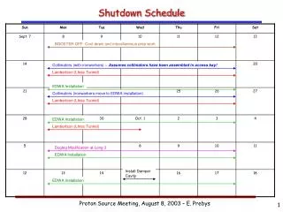
Schedule • P3 downtime schedule P3 Installation Schedule is being updated to integrate with other installation schedules • Using Microsoft Project to track status, we’ll be tracking design and fabrications and kit assemblies for installation Design to Installation Schedule • MFD will staff up two shifts, four crews for 2007 LCLS installation • LCLS 2007 downtime planning schedule • Ponciano’s cable installation plan Cable Installation Schedule • Meetings • Bi-weekly meeting with MFD to discuss 2007 downtime installation status • Weekly meeting with MDF to discuss parts status • Weekly meeting with engineers and designers to discuss design schedule and issues • Weekly meeting with cable plant engineers to discuss 2007 cable installation • Weekly 2007 installation meeting
Documentation Status • BC2 Status • Completed PDR on 12/14/07 • Design is 70% complete • FDR- in April & May 2007 • 18 April 2007, BC2 Support Tables Installation • 2 May 2007, BC2 Vacuum Chamber Installation • 9 May 2007, BC2 Vacuum Supports Installation • 23 May 2007, BC2 Magnet and Support Installation • Drift chambers in fabrication • Everson Tesla is fabricating bend magnets • Support stands released to fabrication
Documentation Status (BC2) Start Mid End
Documentation Status (BC2) • BC2 installation drawings Supports Installation Vacuum Chamber Installation
Documentation Status (L3) • L3 Status • Completed PDR on 12/19/2006 • FDR in May • Completed preliminary installation drawings • Completed all waveguide designs for Linac and request have been submitted to MFD (except long waveguides which were made in 2006) • Kicker Magnet in design, identified commercial ceramic chamber, will order magnet in May
Documentation Status (L3) • Typical installation drawings (sector 25-2)
Product Assurance & Safety • May require lead shielding around BC2 collimator • Using existing shielding in sector 29-4 for the movable collimator • Hoisting & Rigging bend magnets (3600-4300 lbs) in BC2 • Hoisting and rigging for other components (>40 lbs) are similar to 2006 installation • Completed seismic calculations for BC2 supports, also a peer reviewed • Magnets will be reviewed by electrical safety officer
Product Assurance & Safety • Following safety documents are required prior to installation or operation • Safety Overview Approval • Penetration permits • Work authorization approval from LCLS and AD • Earthquake approvals • Building inspection approvals • Electric safety approvals • RP approvals • Non-ionizing approvals
Issues & Concerns • Presented 2007 Installation Readiness Review in March • Committee’s concerns • If the linac installation tasks identified as “low priority” are not implemented then the maximum achievable energy from the Linac will be reduced, this may affect non-LCLS programs. This will also limit or delay the commissioning of systems through BC2 • Readiness of hardware needs to be tracked to ensure availability by the downtime. Components like the kicker magnet, whose design is not yet complete, has no fabrication schedule input by MFD, and the ceramic chamber may have a long lead time. • Pre-installation readiness and component testing should be a high priority to reduce in-field interferences. Space for BC-2 mock-up and testing could help identify technical issues before devices are installed in the tunnel. • Scope definition is vital to a successful installation and the work required for the water system and BSY was not clear. Develop a clear and concise plan for the downtime work. • Integrated schedule is required to determine if scope of work can meet the downtime constraints
Issues & Concerns • Engineers and coordinators • Some of mechanical engineers are still involved in commissioning of LCLS injector system • Depend our commissioning success, if does not go well then is likely more resources brought back into injector • L2 • De-scoping wire scanners “will impact the commissioning significantly - P. Emma” • BC2 design • New articulation and support designs • Not enough time or space to test completed installation assembly in the lab. Plan to test sub-assembly in building 26. • Bend magnets are substantial larger than BC1 bend magnets • L3 design • Designs for BXKIK and OTR-TCav not completed
Issues & Concerns • 2007 downtime installations • 2006 commissioning encountered a few problems with diagnostic components • 2007 new components will be verified and signed off by design engineer, control engineer, alignment group and physicist before installation • Post installation sign off • 2007 downtime 10 weeks vs. 2006 downtime 17 weeks • Reconfiguring 13 Linac girders vs 3 in 2006 • More waveguides in Linac housing • Longer distance from equipment lowered down to installation areas • Davis Bacon Linac installations maybe competing with LTU installations • Water work less than 2006 installation • Hardware and cable installations co-habitat in same area • Not much time for control to check out hardware