Download
1 / 13
130 likes | 255 Vues
This report presents the RF testing of a prototype Triple-GEM detector designed and assembled at LNF. The GEM detector features a standard geometry (10x10 cm²) and includes 40 PADs with a unique cathode and gas window configuration. The study focused on the noise response during RF pulsing in a high-power environment, revealing that effective shielding can significantly reduce noise levels. Detector performance was analyzed using a 55Fe source, demonstrating a reliable signal-to-noise ratio even under RF influence. The results validate the concept for practical applications.

E N D
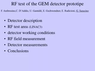
RF test of a small TPGdetector prototype F. Ambrosino,C. D’Addio, F. Caspers, U. Gastaldi, E. Gschwendtner, E. Radicioni, G. Saracino Edda Gschwendtner
Distance mm 10 cathode 3 Drift GEM1 1 T1 GEM2 T2 2 GEM3 1 Induction PAD TPGino • Triple GEM prototype designed and assembled at LNF (G. Bencivenni et al.) • GEM 10X10 cm2 standard geometry CERN • 40 PADs 2.5x1cm2 • 50 mm kapton cathode + 5 mm copper • 20 mm aluminizedmylar gas window • HARP preamplifier • Drift field: 3 kV/cm • T1=T2 field: 3 kV/cm • Induction field: 5 kV/cm • VG1= VG2= VG3=315 V • Total gain ~ 5x10³ • Gas: Ar:CO2 80:20 • 55Fe source (5.9 keV) Edda Gschwendtner
Detector Inside a 2 mm brass shielding: detector preamplifier HV distributor boards Edda Gschwendtner
RF test area at LINAC 3 GEM DETECTOR RF power supply RF pulse: 0.6 ms period of ~1.2 s Edda Gschwendtner
RF test setup L.V. power supply detector to RF tanks ~30cm Detector back to RF power supply ~1m H.V. power supply GEM DETECTOR Edda Gschwendtner
RF field measurement Agilent-HP 11955A biconical antenna to measure the RF field close to the detector area Edda Gschwendtner
RF field measurement 0.6ms Edda Gschwendtner
E-field from RF measurements With the known antenna factor AF and the signal VO of the RF from the antenna measured by the oscilloscope we calculated the electromagentic field E: AF(200MHz) = 16.7 dBm-1 V0=3 V AF= E(Volt/m)/ VO(Volt) 20 log10 E(Vm-1) = 20log10VO (V) + AF(dBm-1) E(Vm-1) = 10(logVo+ AF/20) = VO10AF/20 E=20 V/m Edda Gschwendtner
Noise response of the detector Noise response of the detector (no HV on GEM) Before shielding and grounding: ~400 mV peak to peak inside the RF pulse After shielding and grounding: ~20 mV peak to peak outside the RF pulse ~ 80 mV peak to peak inside the RF pulse With HV on the GEM: Noise response stays the same! RF no influence on detector, only on electronics, cables, etc… Edda Gschwendtner
Detector response to 55Fe X-ray 55Fe source: 5.9 keV peak and 3 keV escape peak. GEM working voltage: 3x315 V RF ON! Self-trigger Nb. This takes away one of the main worries: There is no sign of the photons hitting the GEMS) 55Fe spectrum Background spectrum Edda Gschwendtner
Detector response to 55Fe during RF pulse 55Fe source GEM working voltage: 3x315 V Trigger: RF signal from the antenna 55Fe pulse height: ~300mV Noise: ~40mV! Zoomed signal signal Edda Gschwendtner
Conclusion • We tested a GEM based detector, with cables and grounding not optimized for RF immunity, in the vicinity of the CERN LINAC 3 accelerator (2 RF accelerator tanks of 200 MHz, power supply of ~ 250 KW). • The noise response of the detector can be improved by a factor ~5 (400mV/80mV peak to peak) with home-made shielding of the cables, electronics, etc. • More effective and professional shielding can be provided in the MICE setup. Proof of concept is anyway valid. • The signal to noise ratio of a 55Fe X-ray source is ~8 (300mV/40mV) when the RF is on! • We were able to shield a GEM detector setup such that the presence of RF field at the order of E=20 V/m did not significantly increase the detector noise. Edda Gschwendtner
Pre-amps flexes Solenoid coil Field cage and support TPC active volume Shielding can Sketch-example of shielding principle for final chamber. (need to understand interference with steel shielding for PMTs etc..) All except field cage can be tested in situ early spring. Edda Gschwendtner