68HC11 Polling and Interrupts
68HC11 Polling and Interrupts. Chapter 8. Polling and Interrupts. CPU may need to provide support (called a service) to external devices. How? We can POLL devices We can have an Interrupt system We can have a combination of the two. Polling.

68HC11 Polling and Interrupts
E N D
Presentation Transcript
68HC11 Polling and Interrupts Chapter 8
Polling and Interrupts • CPU may need to provide support (called a service) to external devices. • How? • We can POLL devices • We can have an Interrupt system • We can have a combination of the two
Polling • “Ask” each device sequentially if it needs service. Note, no devices may need servicing during the poll.
Interrupts Device “interrupts” CPU to indicate that it needs service.
68HC11 Interrupts • Interrupt system is “built-in” to 6811 • Special interrupt software instructions • Special interrupt hardware resources • What needs to interrupt? • External Devices • Keyboards, Mouse, Sensors, etc. • Internal Events • Reset, Illegal Operation, User Interrupt, etc
Types of Interrupts • Maskable • The program can choose to “ignore” a maskable interrupt by setting the I bit equal to 1 in the CCR. • This is called “masking” the interrupt. • Setting the I bit = 0 “unmasks” the interrupt, allowing interrupts to be serviced. Condition Code Register
Types of Interrupts • Non-maskable interrupts • A program cannot choose to ignore a non-maskable interrupt. • A non-maskable interrupt is used for events that must always be serviced. • Example: Reset • A special subroutine called an • Interrupt Service Routine (ISR) is used to service the interrupt
Interrupt Service Routine (ISR) • ISR is a special subroutine that is designed to “service” the interrupt • Also called an “interrupt handler” • Let’s examine the interrupt process
Interrupt Process • Interrupt occurs • CPU waits until the current instruction has finished being executed. • Note: PC is pointing to next instruction to execute • All CPU registers including the program counter (PC) and condition code register (CCR) are pushed onto stack • Interrupt bit is set (STI) to mask further interrupts. • In most cases, you don’t want the ISR to itself be interrupted. • The PC is loaded with address of the Interrupt Service Routine (ISR) • ISR is executed. • The last instruction in the ISR must be RTI. • RTI = Return from Interrupt
Return from Interrupt • Your ISR should almost always end with a RTI instruction • RTI – Return from Interrupt • What does RTI do? • Pulls all registers from stack. • The I bit in the pulled CCR is clear, • so interrupts are enabled. • PC contains address of next instruction • Continues interrupted program
LED Circuit Example Switch Light On Light Off
68HC11 LED ExamplePolling Example • Pseudo-code (Polling) • * Use PA0 for Input, PA6 for output • Configure PortA ; • Repeat • IF(PA0=0) then • PA6=0 ; Turn LED OFF • Else • PA6=1; Turn LED ON • EndIF • Until Forever
Symbols ********************************************************** *Symbols Data EQU $0000 ; This is the address of the data space Program EQU $E000 ; This is the start of the program space Reset EQU $FFFE ; This is the reset vector * Constants PORTA EQU $1000 ; Port A Address PACTL EQU $1026 ; Port A Control Register PACONF EQU %00000000 ; This configs PortA for I/O mode LED_BIT EQU %01000000 ; This it the LED bit MASK EQU %00000001 ; This is the input bit mask **********************************************************
Polling Example *************************************************************** * Program ORG Program ; start of Program Start: LDAA #PACONF ; Load Port A conf bits STAA PACTL ; Configure port A * * Let's use If(Bit2 = 0) then LED OFF, Else LED ON * Loop: LDX #PortA ; Load X with address of port A BRCLR 0,X MASK LED_OFF ; Branch to LED_OFF if PA0 = 0 BSET 0,X LED_BIT ; Turn on LED Bit BRA Loop ; Check switch again LED_OFF: BCLR 0,X LED_BIT ; Turn the LED OFF BRA Loop ; Check switch again Note: This program continually checks to switch
68HC11 LED ExampleInterrupt Example • Pseudo-code (Interrupt) • * Use PA6 for output • Configure PortA ; • Enable Interrupts • Execute any program • ISR: *Executed only when interrupt occurs • Read PortA • If PA0=0 Then LED=0 Else LED=1 • Return from Interrupt
Symbols ********************************************************** *Symbols Data EQU $0000 ; This is the address of the data space Program EQU $E000 ; This is the start of the program space Reset EQU $FFFE ; This is the reset vector IRQ EQU $FFF2 ; This is the IRQ vector * Constants PORTA EQU $1000 ; Port A Address PACTL EQU $1026 ; Port A Control Register PACONF EQU %00000000 ; This configs PortA for I/O mode LED_BIT EQU %01000000 ; This is the LED bit Mask EQU %00000001 ; This is the input bit **********************************************************
Interrupt Example *************************************************************** * Program ORG Program ; start of Program Top: LDAA #PACONF ; Load Port A conf bits STAA PACTL ; Configure port A CLI ; Enable interrupts * The main program can do anything * Let’s just wait * Loop: BRA Loop * * This is the ISR. It will only execute when an interrupt occurs * ISR: LDX #PORTA BRCLR 0,X MASK LED_OFF ; If input=0 then Goto LED_OFF LED_ON: BSET 0,X LED_BIT ; Turn LED ON BRA Done ; We are done LED_OFF: BCLR 0,X LED_BIT ; Turn LED OFF Done: RTI ; Return from interrupt
Interrupt Example ORG IRQ ; Need to set ISR vector FDB ISR ORG RESET ; Set Reset interrupt vector FDB Top
Summary PollingInterrupt Switch Input: PA0 PA0 and IRQ Main Program: Checks Switch Anything ISR: Not needed Required
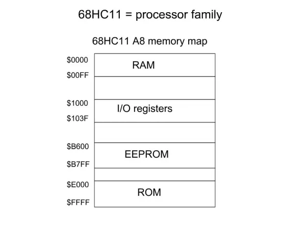
Interrupt Service Routine • Where is the address to the ISR? • The address of the ISR is stored in the Interrupt Vector Table. • 68HC11 Interrupt Vector Table • $FFC0-$FFFF (2 bytes for each interrupt) • Example: • Reset “interrupt” vector is at address • $FFFE:$FFFF
Setting Vectors in Interrupt Vector Table (IVT) • I_Vector EQU Vector Address • ORG I_Vector • FDB ISR • Example: • Reset EQU $FFFE • ORG Reset • FDB TOP
68HC11 Interrupt Vector Table • Serial Systems (SCI and SPI) • SCI: $FFD6:$FFD7 • SPI: $FFD8:$FFD9 • Timer System • IRQ and XIRQ Interrupts • IRQ: $FFF2:FFF3 • XIRQ: $FFF4:FFF5 • Software Interrupts • SWI, Illegal Opcode Fetch • SWI: $FFF6:FFF7 • Hardware Interrupts • COP failure, Clock Monitor Failure, Reset
Software Example IRQ and Reset IRQ Vector :$FFF2:FFF3 Reset Vector: $FFFE:FFFF
IRQ Example • IRQ EQU $FFF2 ; This is the address of the IRQ interrupt • PORTB EQU $1004 ; Port B Address • Zero EQU %00000000 ; 00 • DCHAR EQU %01010101 ; 55 • *************************************************************** • ORG Program ; start of Program • Start: CLI ; Enable interrupts • LDS #Stack ; Set stack pointer • Loop: LDAA #Zero ; Clear byte • STAA PortB • BRA Loop ; Stay here • **************************************************************** • ISR: LDAA #DCHAR • STAA PORTB ; Store A register into port b • RTI ; Return from interrupt • ************************************************************* • * IRQ Vector • ORG IRQ ; Point Assembler to SWI address • FDB ISR • ************************************************************* • * Reset Vector • ORG Reset ;reset vector • FDB Start ;set to start of program If IRQ occurs, then the program at address ISR is executed. If Reset occurs, then the program at address Start is executed.
Nonmaskable Interrupts Section 8.5
Nonmaskable Interrupts • Nonmaskable interrupts cannot be ignored • Several types • External hardware interrupts • Internal hardware interrupts • Software interrupts
68HC11 Nonmaskable Interrupts • Reset • External hardware interrupt • Reset Pin (Active low) • Vector: $FFFE:FFFF • SWI Instruction • Software interrupt • Vector: $FFF6:FFF7 • Computer Operating Failure (COP) • Internal hardware interrupt • Watchdog timer: Chapter 10 • Vector: $FFFA:FFFB
68HC11 Nonmaskable Interrupts • Illegal Opcode Trap • Software Interrupt • Vector: $FFF8:FFF9 • Nonmaskable Interrupt Request (XIRQ) • External hardware interrupt • XIRQ Pin • Vector: $FFF4:FFF5
68HC11 XIRQ Interrupt • Nonmaskable Interrupt Request (XIRQ) • External hardware interrupt • On reset, the XIRQ interrupt is disabled, the programmer must enable it by clearing the XIRQ bit. • E.g. During the boot process • Once the XIRQ is enabled, the programmer cannot disable it • E.g. Users cannot turn this off!!!! • External hardware interrupt • XIRQ Pin • Vector: $FFF4:FFF5
68HC11 Interrupt Instructions • SEI: SEt Interrupt mask: Set I bit to 1 • Disables (masks) all maskable interrupts • CLI: CLear Interrupt mask: Reset I bit to 0 • Enables (unmasks) all maskable interrupts • SWI: SoftWare Interrupt • Generates software interrupt • WAI: WAit for Interrupt • Pushes all registers onto stack • Places CPU into wait state • Interrupt will “wake-up” controller • RTI: Return from Interrupt • Pulls all registers from stack • Executes interrupted program
Advanced Interrupts Section 8.7
Polling • “Ask” each device sequentially if it needs service. However, no devices may need servicing.
Interrupts Device “interrupts” CPU to indicate that it needs service.
Multiple Devices Use Interrupt to indicate that a device needs to be serviced. ISR then “polls” each device to determine who needs service
Multiple Devices May need external logic to “arbitrate” devices
Priority with Multiple Devices • What if two devices request an interrupt at the same time? • Use a “priority” scheme to determine which device gets serviced first. • 68HC11 Built-in Priority Scheme • IRQ • Real Time Interrupt • Timer Input Capture – 1-3 • Timer Output Compare – 1-5 • Timer Overflow • Pulse Accumulator • Serial Interface • Can be changed via the HPRIO ($103C) register