Arithmetic Logic Unit ALU
Arithmetic Logic Unit ALU. The Bus Concept. CPU Building Blocks. Registers (IR, PC, ACC) Control Unit (CU) Arithmetic Logic Unit (ALU). The Simplest Computer Building Blocks. Instruction Register (IR). Program Counter (PC). Control Unit (CU). ALU. Status Register (FLAG).

Arithmetic Logic Unit ALU
E N D
Presentation Transcript
CPU Building Blocks • Registers (IR, PC, ACC) • Control Unit(CU) • Arithmetic Logic Unit (ALU)
The Simplest Computer Building Blocks Instruction Register (IR) Program Counter (PC) Control Unit (CU) ALU Status Register (FLAG) Accumulator (ACC) CPU RAM
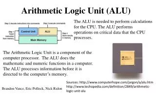
What’s ALU? ALU stands for: Arithmetic Logic Unit ALU is a digital circuit that performs Arithmetic (Add, Sub, . . .) and Logical (AND, OR, NOT) operations. John Von Neumann proposed the ALU in 1945 when he was working on EDVAC.
Typical Schematic Symbol of an ALU • A and B: the inputs to the ALU(aka operands) • R: Output or Result • F: Code or Instruction from the Control Unit (aka as op-code) • D: Output status; it indicates cases such as: • carry-in • carry-out, • overflow, • division-by-zero
Let’s Build a 1-Bit ALU This is an one-bit ALU which can do Logical AND and Logical OR operation. Result = a AND b when operation = 0 Result = a OR b when operation = 1 The operation line is the input of a MUX.
Adding a full adder to our ALU Building a 1-Bit ALU (cont’d)
The Goal ALU 32 bit operand 32 bit result 32 bit operand Control (operation selection)
Starting Small • We can start by designing a 1 bit ALU. • Put a bunch of them together to make larger ALUs. • building a larger unit from a 1 bit unit is simple for some operations, can be tricky for others. • Bottom-Up approach: • build small units of functionality and put them together to build larger units.
1 bit AND/OR machine • We want to design a single box that can compute either AND or OR. • We will use a control input to determine which operation is performed. • Name the control “Op”. • if Op==0 do an AND • if Op==1 do an OR
Truth Table For 1-bit AND/OR A B Result Op Op=0: Result is A•B Op=1: Result is A+B
Logic for 1-Bit AND/OR • We could derive SOP or POS and build the corresponding logic. • We could also just do this: • Feed both A and B to an OR gate. • Feed A and B to an AND gate. • Use a 2-input MUX to pick which one will be used. • Op is the selection input to the MUX.
Logic Design for 1-Bit AND/OR Mux A Result B Op
Addition • We need to build a 1 bit adder • compute binary addition of 2 bits. • We already know that the result is 2 bits. This is addition, not logical OR! A + B O0 O1
One Implementation A O0 B A B O1 A B
Binary addition and our adder 1 1 Carry What we really want is something that can be used to implement the binary addition algorithm. • O0 is the carry • O1 is the sum 01001 + 01101 10110
What about the second column? 1 1 Carry 01001 + 01101 • We are adding 3 bits • new bit is the carry from the first column. • The output is still 2 bits, a sum and a carry 10110
Logic Design for new adder • We can derive SOP expressions from the truth table. • We can build a combinational circuit that implements the SOP expressions. • We can put it in a box and give it a name.
New Component: Adder Carry In adder A Sum B Carry Out
1 Bit ALU • Combine the AND/OR with the adder. • We must now use a 4-input MUX with 2 selection inputs. AND OR add
Building a 32 bit ALU • 64 inputs • 3 different Operations (AND,OR,add). • 32 bit output A0 A1 … A31 B0 B1 … B31 … … Op … Result R0 R1 … R31
Ripple Carry Adder • Carry out from ALU0 is sent to carry in of ALU1 • How long will it take for the result to become available? • the CarryOuts must propagate through all 32 1-Bit ALUs.
New Operation: Subtraction • Subtraction can be done with an adder: A - B can be computed as A + -B • To negate B we need to: • invert the bits. • add 1
Negating B in the ALU • We can negate B by in the ALU by: • providing B to the adder. • need a selection bit to do this. • To add 1, just set the initial carry in to 1!
Uses for our ALU • addition, subtraction, OR and AND instructions can be implemented with our ALU. • we still need to get the right values to the ALU and set control lines. • We can also support the slt instruction. • need to add a little more to the 1 bit ALU.
Supporting slt slt needs to compare 2 numbers. • comparison requires a subtraction. if A-B is negative, then A<B is true. otherwise A<B is false. True: output should be 0000000…001 False: output should be 0000000…000 This is what slt stores in the dest. register
slt Strategy • To compute slt A B: • subtract B from A (set Binvert and the L.S. Carry In to 1. • Result for all 1-bit ALUs except the LS should always be 0. • Result for the LS 1-bit ALU should be the result bit from the MS 1-bit ALU! LS: Least significant (rightmost) MS: Most significant (leftmost)
New 1-bit ALU B i n v e r t O p e r a t i o n C a r r y I n a 0 1 R e s u l t b 0 2 1 L e s s 3 C a r r y O u t
B i n v e r t O p e r a t i o n C a r r y I n a 0 1 R e s u l t b 0 2 1 L e s s 3 S e t O v e r f l o w O v e r f l o w d e t e c t i o n b . MS ALU
New 32-bit ALU • Less input is 0 for all but the LS. • Result of addition in the MS ALU is fed back to the Less input of the LS ALU
Speed is important. • Using a ripple carry adder the time it takes to do an addition is too long. • each 1-bit ALU has something like 4 levels of gates. • The input to the ith ALU includes an output from the i-1th ALU. • For 32 bits we have something like 128 gate delays before the addition is complete.
Strategies for speeding things up. • We could derive the truth table for each of the 32 result bits as a function of 64 inputs. • We know we can build SOP expressions for each and implement using 2 levels of gates. • This might be a good test question! • don’t worry, you would need so much paper I couldn’t carry the tests to class…
A more realistic approach • The problem is the ripple • The last carry-in is takes a long time to compute. • We can try to compute the carry-in bits as fast as possible • this is called carry lookahead • It turns out we can easily compute the carry-in bits much faster (but not in constant time).
Carry In Analysis • CarryIni is an input to the ith 1 bit adder. • CarryOuti-1 is connected to CarryIni • We know about how to compute the CarryOuts
Computing Carry Bits • CarryIn0 is an input to the adder. • we don’t compute this – it’s an input. • CarryIn1 depends on A0, B0 and CarryIn0: CarryIn1 = (B0• CarryIn0) + (A0 • CarryIn0)+(A0 • B0) SOP: Requires 2 levels of gates
CarryIn2 CarryIn2 = (B1• CarryIn1) + (A1 • CarryIn1)+(A1 • B1) We can substitute for CarryIn1 and get this mess: CarryIn2 = (B1• B0• CarryIn0) + (B1• A0 • CarryIn0)+(B1• A0 • B0) + (A1 • B0• CarryIn0) + (A1 • A0 • CarryIn0)+(A1 • A0 • B0)+(A1 • B1) The size of these expressions will get too big (that’s the whole problem!).
Another way to describe CarryIn Ci+1 = (Bi• Ci) + (Ai • Ci)+(Ai • Bi) = (Ai • Bi) + (Ai + Bi) •Ci Ai • Bi : Call this Generate (Gi) Ai + Bi : Call this Propagate (Pi) Ci+1 = Gi + Pi• Ci
Ci+1 = Gi + Pi• Ci Gi =Ai • Bi Pi =Ai + Bi Generate and Propagate • When Ai and Bi are both 1, Gi becomes a 1. • a CarryOut is generated. • If Pi is a 1, any Carry in is propagated to Carry Out.
Using Gi and Pi C1 = G0+P0•C0 C2 = G1+P1•C1 = G1+ P1• (G0+P0•C0) = G1+ P1• G0 + P1• P0•C0 C3 = G2 + P2•G1 + P2•P1•G0 + P2•P1•P0•C0
Implementation • Expression is still too big to handle (for 32 bits). • We can minimize the time needed to compute all the CarryIn bits for a 4 bit adder. • Connect a bunch of 4 bit adders together and treat CarryIns to these adders in the same manner.
Binary Multiplication multiplicand 1000 x 1001 1000 0000 0000 1000 1001000 multiplier product
1 . T e s t M u l t i p l i e r 0 1 a . A d d m u l t i p l i c a n d t o p r o d u c t a n d p l a c e t h e r e s u l t i n P r o d u c t r e g i s t e r 2 . S h i f t t h e M u l t i p l i c a n d r e g i s t e r l e f t 1 b i t 3 . S h i f t t h e M u l t i p l i e r r e g i s t e r r i g h t 1 b i D o n e S t a r t M u l t i p l i e r 0 = 1 M u l t i p l i e r 0 = 0 t N o : < 3 2 r e p e t i t i o n s 3 2 n d r e p e t i t i o n ? Y e s : 3 2 r e p e t i t i o n s