Download
1 / 16
160 likes | 441 Vues
Understand ALUs as the main computation units in computers. Learn about functions, architecture, data paths, control paths, and ALU integration in processors. Explore ALU operations, circuit design, and implementation using ROMs and RAMs for various arithmetic and logic functions.

E N D
CS 151Digital Systems DesignLecture 33Arithmetic Logic Unit (ALU)
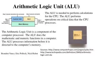
Overview • Main computation unit in most computer systems • ALUs perform a vaiety of different functions • Add, subtract, OR, AND… • Example: ALU chip (74LS382) • Has data and control inputs • Individual chips can be chained together to make larger ALUs • ALUs are important parts of datapaths • ROMs often are usd in the control path • Build a data and control path
ROM-based Moore Machine Timing • What is the maximum clock frequency of this circuit? • Does this circuit satisfy hold time constraints? ROM ROM
Adder Subtract Arithmetic Logic Unit DataA DataB • Arithmetic logic unit functions • Two multi-bit data inputs • Function indicates action (e.g. add, subtract, OR…) • DataOut is same bit width as multi-bit inputs (DataA and DataB) • ALU is combinational • Conditions indicate special conditions of arithmetic activity (e.g. overflow). Function ALU Conditions DataOut Think of ALU as a number of other arithmetic and logic blocks in a single box! Functionselects the block … AND
ALU Integrated Circuit • Integrated circuit – off-the-shelf components • Examine the functionality of this ALU chip Performs 8 functions
Example • Determine the 74HC382 ALU outputs for the following inputs: S2S1S0=010, A3A2A1A0=0100, B3B2B1B0=0001, and CN=1. • Function code indicates subtract • 0100 – 0001 = 0011 • Change the select code to 101 and repeat. • Function code indicates OR • 0100 OR 0001 = 0101 Synchronize ALU with a clock DataA DataB Function ALU Conditions DataOut
Expanding the ALU • Multi-bit ALU created by connecting carry output of low-order chip to carry in of high order Eight-bit ALU formed from 2 four-bit ALUs
Datapath components • Tri-state buffer • Loadable register If Enable asserted, Out = In Otherwise Out open-circuit In Out Enable Clk Load Data stored on rising edge if Load is asserted (e.g. Load = 1)
Computation in a Typical Computer • Control logic often implemented as a finite state machine (including ROMs) • Datapath contains blocks such as ALUs, registers, tri-state buffers, and RAMs • In a processor chip often a 5 to 1 ratio of datapath to control logic
LoadA A B LoadB ALU Function Using a Datapath • Consider the following computation steps • ADD A, B and put result in A • Subtract A, B and put result in B • OR A, B put result in A • Repeat starting from step 1 Determine values for Function, LoadA, LoadB
Modeling Control as a State Machine • Consider the following computation steps • ADD A, B and put result in A • Subtract A, B and put result in B • OR A, B put result in A • Repeat starting from step 1 Determine values for Function, LoadA, LoadB Model control as a state machine. Determine control outputs for each state S0 S2 S1
Modeling Control as a State Machine • Consider the following computation steps • ADD A, B and put result in A • Subtract A, B and put result in B • OR A, B put result in A • Repeat starting from step 1 States S0 = 00 S1 = 01 S2 = 10 Present State Next State Function LoadA LoadB 00 01 011 1 0 01 10 010 0 1 10 00 101 1 0 We know how to implement this using an SOP. Can we use a ROM?
0101110 ROM 1001001 0010110 00 01 PS 10 NS Function, LoadA, LoadB ROM Implementation of State Machine Present State Next State Function LoadA LoadB 00 01 0111 0 01 100100 1 10 001011 0 States S0 = 00 S1 = 01 S2 = 10 Note: No minimization! One line in ROM for each state
ALU Putting the Control and Datapath Together ROM 00 0101110 01 1001001 10 0010110 PS NS LoadA A B LoadB 3 Function
ALU What if we replaced the ROM with RAM? RAM 00 Looks likesoftware! 0101110 01 1001001 10 0010110 PS NS LoadA A B LoadB 3 Function Possible to implement different functions! Program the RAM to perform different sequences
Summary • ALU circuit can perform many functions • Combinational circuit • ALU chips can be combined together to form larger ALU chips • Remember to connect carry out to carry in • ALUs form the basis of datapaths • ROMs can form the basis of control paths • Combine the two together to build a computing circuit • Next time: more data and control paths