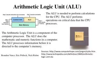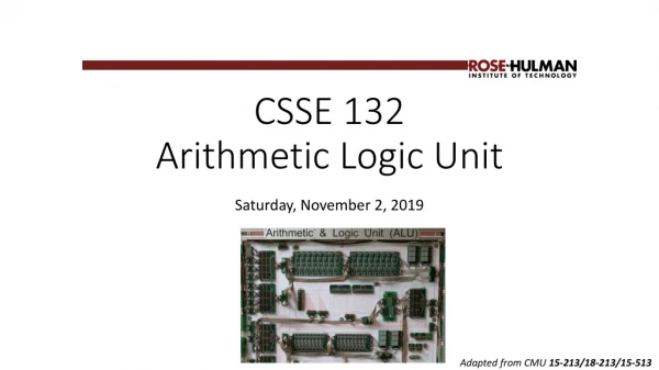
Arithmetic Logic Unit (ALU)
This guide explores the fundamentals of the Arithmetic Logic Unit (ALU) and its role in computing, focusing on the design of a 4-bit adder circuit. It illustrates how to construct a circuit for adding two 4-bit integers, addressing binary addition, handling overflow, and representing negative numbers using two's complement. By breaking down the design into logical steps, including truth tables and Boolean expressions, the guide emphasizes how to implement an efficient adder circuit and discusses the principles that can be scaled to larger systems, such as a 128-bit adder.

Arithmetic Logic Unit (ALU)
E N D
Presentation Transcript
Arithmetic Logic Unit (ALU) Introduction to Computer Yung-Yu Chuang with slides by Sedgewick & Wayne (introcs.cs.princeton.edu), Nisan & Schocken (www.nand2tetris.org) and Harris & Harris (DDCA)
Let's Make an Adder Circuit • Goal. x + y = z for 4-bit integers. • We build 4-bit adder: 9 inputs, 4 outputs. • Same idea scales to 128-bit adder. • Key computer component. 1 1 1 0 2 4 8 7 + 3 5 7 9 6 0 6 6
0 0 0 1 1 0 0 1 0 1 0 1 0 1 1 1 0 1 1 1 1 1 0 1 1 0 1 1 1 1 0 0 1 0 no overflow overflow Binary addition Assuming a 4-bit system: + + • Algorithm: exactly the same as in decimal addition • Overflow (MSB carry) has to be dealt with.
1 1 0 1 = -3 Representing negative numbers (4-bit system) • The codes of all positive numbers begin with a “0” • The codes of all negative numbers begin with a “1“ • To convert a number: leave all trailing 0’s and first 1 intact,and flip all the remaining bits 0 0000 1 0001 1111 -1 2 0010 1110 -2 3 0011 1101 -3 4 0100 1100 -4 5 0101 1011 -5 6 0110 1010 -6 7 0111 1001 -7 1000 -8 Example: 2 - 5 = 2 + (-5) = 0 0 1 0 + 1 0 1 1
Let's Make an Adder Circuit • Step 1. Represent input and output in binary. 1 1 0 0 0 0 1 0 + 0 1 1 1 1 0 0 1 x3 x2 x1 x0 + y3 y2 y1 y0 z3 z2 z1 z0
Let's Make an Adder Circuit cin cout • Goal. x + y = z for 4-bit integers. • Step 2. [first attempt] • Build truth table. • Q. Why is this a bad idea? • A. 128-bit adder: 2256+1 rows >> # electrons in universe! x3 x2 x1 x0 + y3 y2 y1 y0 z3 z2 z1 z0 4-Bit Adder Truth Table c0 x3 x2 x1 x0 y3 y2 y1 y0 z3 z2 z1 z0 0 0 0 0 0 0 0 0 0 0 0 0 0 0 0 0 0 0 0 0 0 1 0 0 0 1 0 0 0 0 0 0 0 1 0 0 0 1 0 0 0 0 0 0 0 0 1 1 0 0 1 1 28+1 = 512 rows! 0 0 0 0 0 0 1 0 0 0 1 0 0 . . . . . . . . . . . . . 1 1 1 1 1 1 1 1 1 1 1 1 1
1-bit half adder • We add numbers one bit at a time. x ADD c y s y x s c
1-bit full adder x y y x s Cin Cout ADD Cin Cout s
Let's Make an Adder Circuit c3 c2 c1 c0 = 0 cout • Goal. x + y = z for 4-bit integers. • Step 2. [do one bit at a time] • Build truth table for carry bit. • Build truth table for summand bit. x3 x2 x1 x0 + y3 y2 y1 y0 z3 z2 z1 z0 Carry Bit Summand Bit xi yi ci ci+1 xi yi ci zi 0 0 0 0 0 0 0 0 0 0 1 0 0 0 1 1 0 1 0 0 0 1 0 1 0 1 1 1 0 1 1 0 1 0 0 0 1 0 0 1 1 0 1 1 1 0 1 0 1 1 0 1 1 1 0 0 1 1 1 1 1 1 1 1
Let's Make an Adder Circuit • Goal. x + y = z for 4-bit integers. • Step 3. • Derive (simplified) Boolean expression. Carry Bit Summand Bit xi yi ci ci+1 MAJ xi yi ci zi ODD 0 0 0 0 0 0 0 0 0 0 0 0 1 0 0 0 0 1 1 1 0 1 0 0 0 0 1 0 1 1 0 1 1 1 1 0 1 1 0 0 1 0 0 0 0 1 0 0 1 1 1 0 1 1 1 1 0 1 0 0 1 1 0 1 1 1 1 0 0 0 1 1 1 1 1 1 1 1 1 1
Let's Make an Adder Circuit • Goal. x + y = z for 4-bit integers. • Step 4. • Transform Boolean expression into circuit. • Chain together 1-bit adders.
Subtractor • Subtractor circuit: z = x – y. • One approach: design like adder circuit
Subtractor • Subtractor circuit: z = x – y. • One approach: design like adder circuit • Better idea: reuse adder circuit • 2’s complement: to negate an integer, flip bits, then add 1
Subtractor • Subtractor circuit: z = x – y. • One approach: design like adder circuit • Better idea: reuse adder circuit • 2’s complement: to negate an integer, flip bits, then add 1
Shifter Only one of them will be on at a time. s0 s1 s2 s3 SHIFT x0 x1 x2 x3 z0 z1 z2 z3 4-bit Shifter
Shifter z0 = s0‧x0 + s1‧0 + s2‧0 + s3‧0 z1 = s0‧x1 + s1‧x0 + s2‧0 + s3‧0 z2 = s0‧x2 + s1‧x1 + s2‧x0 + s3‧0 z3 = s0‧x3 + s1‧x2 + s2‧x1 + s3‧x0
Shifter z0 = s0‧x0 + s1‧0 + s2‧0 + s3‧0 z1 = s0‧x1 + s1‧x0 + s2‧0 + s3‧0 z2 = s0‧x2 + s1‧x1 + s2‧x0 + s3‧0 z3 = s0‧x3 + s1‧x2 + s2‧x1 + s3‧x0
N-bit Decoder • N-bit decoder • N address inputs, 2N data outputs • Addresses output bit is 1; all others are 0
N-bit Decoder • N-bit decoder • N address inputs, 2N data outputs • Addresses output bit is 1; all others are 0
2-Bit Decoder Controlling 4-Bit Shifter r0r1 • Ex. Put in a binary amount to shift.
Arithmetic Logic Unit • Arithmetic logic unit (ALU). Computes all operations in parallel. • Add and subtract. • Xor. • And. • Shift left or right. • Q. How to select desired answer?
1 Hot OR • 1 hot OR. • All devices compute their answer; we pick one. • Exactly one select line is on. • Implies exactly one output line is relevant. adder xor x.1 = x x.0 = 0 x + 0 = x shifter
1 Hot OR x.1 = x x.0 = 0 x + 0 = x adder decoder xor shift
Bus 16-bit bus • Bundle of 16 wires • Memory transfer Register transfer 8-bit bus • Bundle of 8 wires • TOY memory address 4-bit bus • Bundle of 4 wires • TOY register address
Bitwise AND, XOR, NOT • Bitwise logical operations • Inputs x and y: n bits each • Output z: n bits • Apply logical operation to each corresponding pair of bits
TOY ALU • TOY ALU • Big combinational logic • 16-bit bus • Add, subtract, and, xor, shift left, shift right, copy input 2
Device Interface Using Buses 16-bit words for TOY memory • Device. Processes a word at a time. • Input bus. Wires on top. • Output bus. Wires on bottom. • Control. Individual wires on side.
ALU • Arithmetic logic unit. • Add and subtract. • Xor. • And. • Shift left or right. • Arithmetic logic unit. • Computes all operations in parallel. • Uses 1-hot OR to pick each bit answer. How to convert opcode to 1-hot OR signal?
Hack ALU out(x, y,control bits) = x+y, x-y, y–x, 0, 1, -1, x, y, -x, -y, x!, y!, x+1, y+1, x-1, y-1, x&y, x|y
The ALU in the CPU context (a sneak preview of the Hack platform) c1,c2, … ,c6 D D register a out ALU A A register A/M Mux RAM (selected register) M
Perspective • Combinational logic • Our adder design is very basic: no parallelism • It pays to optimize adders • Our ALU is also very basic: no multiplication, no division • Where is the seat of more advanced math operations?a typical hardware/software tradeoff.