Arithmetic Logic Unit (ALU)
Arithmetic Logic Unit (ALU). Anna Kurek CS 147 Spring 2008.

Arithmetic Logic Unit (ALU)
E N D
Presentation Transcript
Arithmetic Logic Unit (ALU) Anna Kurek CS 147 Spring 2008
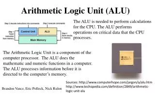
An Arithmetic Logic Unit (ALU) is a digital circuit that performs arithmetic and logical operations. The ALU is a fundamental building block of the central processing unit of a computer, and even the simplest microprocessor contains one for purposes such as maintaining timers.
Early development • In 1946, John von Neumann worked with his colleagues in designing a computer for the Princeton Institute of Advanced Studies (IAS). The IAS computer became the prototype for many later computers. In the proposal, von Neumann outlined what he believed would be needed in his machine, including an ALU. • Von Neumann stated that an ALU is a necessity for a computer because it is guaranteed that a computer will have to compute basic mathematical operations, including addition, subtraction, multiplication, and division. He therefore believed it was "reasonable that [the computer] should contain specialized organs for these operations."
Numerical systems • An ALU must process numbers using the same format as the rest of the digital circuit. For modern processors, that almost always is the two's complement binary number representation. Early computers used a wide variety of number systems, including one's complement, sign-magnitude format, and even true decimal systems, with ten tubes per digit. • ALUs for each one of these numeric systems had different designs, and that influenced the current preference for two's complement, as this is the representation that makes it easier for the ALUs to calculate additions and subtractions.
Practical overview • Most of a processor's operations are performed by one or more ALU. An ALU loads data from input registers, executes, and stores the result into an output register. A Control Unit tells the ALU what operation to perform on the data. Other mechanisms move data between these registers and memory.
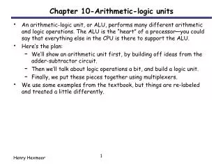
A typical schematic symbol for an ALU • A and B are the inputs to the ALU; it is the • data to be operated on (called operands); • - R is the output, result of the computation; • - F is the code (instruction) • from the Control Unit; • - D is an output status, also • known as condition code, • it indicates cases such • as carry-in, carry-out, • overflow, • division-by-zero, etc.
Simple operations • Most ALUs can perform the following operations: • Integer arithmetic operations (addition, subtraction, and sometimes multiplication and division, though this is more expensive) • Bitwise logic operations (AND, NOT, OR, XOR) • Bit-shifting operations (shifting or rotating a word by a specified number of bits to the left or right, with or without sign extension). Shifts can be interpreted as multiplications by 2 and divisions by 2.
Complex operations • An engineer can design an ALU to calculate any operation, however it is complicated; the problem is that the more complex the operation, the more expensive the ALU is, the more space it uses in the processor, and the more power it dissipates, etc. • Therefore, engineers always calculate a compromise, to provide for the processor (or other circuits) an ALU powerful enough to make the processor fast, but yet not so complex as to become prohibitive.
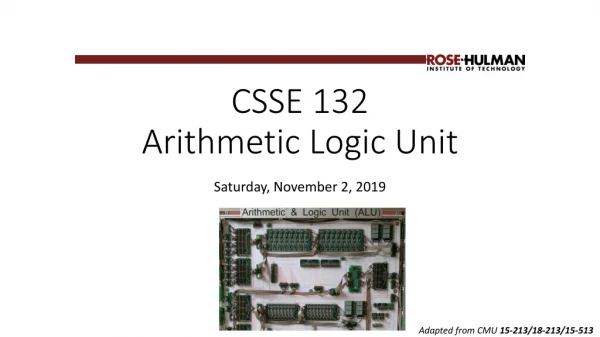
A 1-Bit ALU The logical operations are easiest, because they map directly onto the hardware components. The 1-bit logical unit for AND and OR looks like figure below. The multiplexor on the right then selects a AND b or a OR b, depending on whether the value of Operation is 0 or 1. The line that controls the multiplexor is shown in color to distinguish it from the lines containing data. In the figure below control and output lines of the multiplexor were renamed to names that reflect the function of the ALU.
The next function to include is addition. An adder must have two inputs for the operands and a single-bit output for the sum. There must be a second output to pass on the carry, called CarryOut. Since the CarryOut from the neighbor adder must be included as an input, we need a third input. This input is called CarryIn. Figure below shows the inputs and the outputs of a 1-bit adder.
We can express the output functions CarryOut and Sum as logical equations, and these equations can in turn be implemented with logic gates. Logic equation: CarryOut = (b * CarryIn) + (a * CarryIn) + (a * b) Logic gates:
Figure below shows a 1-bit ALU derived by combining the adder with the earlier components. Sometimes designers also want the ALU to perform a few more simple operations, such as generating 0. The easiest way to add an operation is to expand the multiplexor controlled by the Operation line and, for this example, to connect 0 directly to the new input of that expanded multiplexor.
Subtraction is the same as adding the negative version of an operand, and this is how adders perform subtraction. The shortcut for negating a two’s complement number is to invert each bit (sometimes called the one’s complement) and then add 1. To invert each bit, we simply add a 2:1 multiplexor that chooses between b and b’.
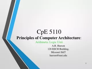
A 1-bit ALU that performs AND, OR, and addition on a and b or a and b. By selecting a (Ainvert = 1) and b (Binvert = 1), we get a NOR b instead of a AND b.
A 32-Bit ALU Now that we have completed the 1-bit ALU, the full 32-bit ALU is created by connecting adjacent “black boxes.” Using xi to mean the ith bit of x, figure below shows a 32-bit ALU. The adder created by directly linking the carries of 1-bit adders is called a ripple carry adder.