Frequency Response of Discrete-Time Systems
340 likes | 1.27k Vues
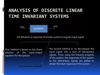
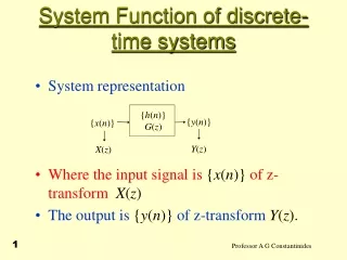
Frequency Response of Discrete-Time Systems. Complex Exponentials. Two-sided complex exponential z n when input into LTI systems Output will be same complex exponential weighted by H ( z ) Provided that z is in region of convergence for H ( z )

Frequency Response of Discrete-Time Systems
E N D
Presentation Transcript
Complex Exponentials • Two-sided complexexponential zn wheninput into LTI systems Output will be same complexexponential weighted by H(z) Provided that z is in region ofconvergence for H(z) • When we specialize the z-domain to frequency domain, the magnitude of H(z) will control which frequencies are attenuated or passed
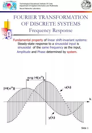
Frequency Response for LTI Systems • Continuoustime • Discretetime • Real-valued impulse response: H(e-jω) = H*(ejω) Input Output
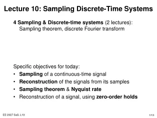
Response to Sampled Sinusoids • Start with a continuous-time sinusoid • Sample it every Tsseconds (see slide 7-6) • We show discrete-time sinusoid with • Resulting in • Discrete-time frequency is equal to continuous-time frequency multiplied by sampling period
Example • Calculate the frequency response of the system given as a difference equation as • Assuming zero initial conditions we take the z-transform of both sides • Since pole is inside unit circle,
Example • Group real and imaginary parts • Absolute value (magnituderesponse) • Find angle(phase response)
Magnitude and Phase Responses • Output of system for input cos(W0k) is simply Magnitude response Phase response
Discrete-time Frequency Response • As in previous example, frequency response of a discrete-time system is periodic with 2 Why? Frequency response is function of complex exponential which has period of 2 : • Absolute value of discrete-time frequency response is even and angle is odd symmetric Discrete-time sinusoid is symmetric around
Aliasing and Sampling Rate • Continuous-time sinusoid can have a frequency from 0 to infinity • By sampling a continuous-time sinusoid, • Discrete-time frequency unique from 0 to We only can represent frequencies up to half of the sampling frequency. Higher frequencies exist would be “wrapped” to some other frequency in the range.
Im Re Effect of Poles and Zeros of H(z) • The z-transform of a difference equation can be written in general form as • Complex number as vector in complex plane z and zi are both complex numbers Their difference is also a complexnumber (vector in complex plane)
Im x o o Re x Effect of Poles and Zeros of H(z) • Each difference term in H(z) may be represented as a complex number in polar form Magnitude is distance ofpole/zero to chosen point(frequency) on unit circle Angle is angle of vector withrespect to horizontal axis
Digital Filter Design • Poles near unit circle indicate filter’s passband(s) • Zeros on/near unit circle indicate stopband(s) • Biquad with zeros z0 and z1, and poles p0 and p1 Transfer function Magnitude response |a – b| is distance between complex numbers a and b Distance from point on unit circle ej and pole location p0
Im(z) Im(z) Im(z) O O X X X O Re(z) Re(z) Re(z) O X X X O O Digital Filter Design Examples • Transfer function • Poles (X) & zeros (O) in conjugate symmetric pairs For coefficients in unfactored transfer function to be real • Filters below have what magnitude responses? lowpasshighpass bandpass bandstop allpass notch? Zeros are on the unit circle Poles have radius r Zeros have radius 1/r
DSP First Demonstrations • IIR Filters (Chapter 8) • Three-domain demonstrations IIR filter with one pole IIR filter with one pole and one zero Radial movement of poles (second-order section) • Z-to-Freq demonstration Figure 4: Movie takes points on unit circle to create magnitude response (double click on plot to start animation) Last figure: Movie takes slice of 3-D view of the z-domain to create magnitude response (double click on plot to start animation)
DSP First Demonstrations • BIBO stable causal systems All poles inside unit circle • Filter amplitude response at Enhance it by placing a pole close to ej Suppress it by placing a zero close to or at ej • Poles/zeros at origin Do not affect amplitude response Add a phase of (– T ) which is a pure delay • Poles and zeros can cancel each other’s effect if placed close together
wT wT o x x - -/2 wT wT x o x x o x - - Effect of Poles/Zeros