Introduction to IA-32 Paging Scheme in Intel x86 Architecture
280 likes | 340 Vues
Learn about dynamic address remapping for virtual memory, paging benefits for multitasking, Intel x86 paging schemes, and how to enable and manage paging in IA-32 architecture.

Introduction to IA-32 Paging Scheme in Intel x86 Architecture
E N D
Presentation Transcript
IA32 Paging Scheme Introduction to the Intel x86’s support for “virtual” memory
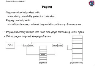
What is ‘paging’? • It’s a scheme for dynamically remapping addresses for fixed-size memory-blocks Physical address-space Virtual address-space
What’s ‘paging’ good for? • For efficient ‘time-sharing’ among multiple tasks, an operating system needs to have several programs residing in main memory at the same time • To accomplish this using actual physical memory-addressing would require doing address-relocation calculations each time a program was loaded (to avoid conflicting with any addresses already being used)
Why use ‘paging’? • Use of ‘paging’ allows ‘relocations’ to be done just once (by the linker), and every program can ‘reuse’ the same addresses Task #3 Task #1 physical memory Task #2
How to enable paging Control Register CR0 P G C D N W A M W P N E E T T S E M M P P E Protected-Mode must be enabled (PE=1) Then ‘Paging’ can be enabled (set PG=1) # Here is how you can enable paging (if already in protected-mode) mov %cr0, %eax # get current machine status bts $31, %eax # turn on the PE-bit’s image mov %eax, %cr0 # put modified status in CR0 jmp pg # now flush the prefetch queue pg: # but you had better prepare your ‘mapping-tables’ beforehand!
Several ‘paging’ schemes • Intel’s design for ‘paging’ has continued to evolve since its introduction in 80386 CPU • New processors support the initial design, as well as several optional extensions • We shall describe the initial design which is simplest and remains as the ‘default’ • It is based on subdividing the entire 4GB virtual address-space into 4KB blocks
Terminology • The 4KB memory-blocks are called ‘page frames’ -- and they are non-overlapping • Therefore each page-frame begins at a memory-address which is a multiple of 4K • Remember: 4K = 4 x 1024 = 4096 = 212 • So the address of any page-frame will have its lowest 12-bits equal to zeros • Example: page six begins at 0x00006000
Control Register CR3 • Register CR3 is used by the CPU to find the tables in memory which will define the address-translation that it should employ • This table is called the ‘Page Directory’ and its address must be ‘page-aligned’ 31 0 Physical Address of the Page-Directory
Page-Directory • The Page-Directory occupies one frame, so it has room for 1024 4-byte entries • Each page-directory entry may contain a pointer to a further data-structure, called a Page-Table (also page-aligned 4KB size) • Each Page-Table occupies one frame and has enough room for 1024 4-byte entries • Page-Table entries may contain pointers
Two-Level Translation Scheme PAGE TABLES PAGE DIRECTORY PAGE FRAMES CR3
Address-translation • The CPU examines any virtual address it encounters, subdividing it into three fields 31 22 21 12 11 0 index into page-directory index into page-table offset into page-frame 10-bits 10-bits 12-bits This field selects one of the 1024 array-entries in the Page-Directory This field selects one of the 1024 array-entries in that Page-Table This field provides the offset to one of the 4096 bytes in that Page-Frame
Page-Level ‘protection’ • Each entry in a Page-Table can assign a collection of ‘attributes’ to the Page-Frame that it points to; for example: • The P-bit (page is ‘present’) can be used by the operating system to support its implementation of “demand paging” • The W/R-bit can be used to mark a page as ‘Writable’ or as ‘Read-Only’ • The U/S-bit can be used to mark a page as ‘User accessible’ or as ‘Supervisor-Only’
Format of a Page-Table entry 31 12 11 10 9 8 7 6 5 4 3 2 1 0 PAGE-FRAME BASE ADDRESS AVAIL 0 0 D A P C D P W T U W P LEGEND P = Present (1=yes, 0=no) W = Writable (1 = yes, 0 = no) U = User (1 = yes, 0 = no) A = Accessed (1 = yes, 0 = no) D = Dirty (1 = yes, 0 = no) PWT = Page Write-Through (1=yes, 0 = no) PCD = Page Cache-Disable (1 = yes, 0 = no)
Format of a Page-Directory entry 31 12 11 10 9 8 7 6 5 4 3 2 1 0 PAGE-TABLE BASE ADDRESS AVAIL 0 P S 0 A P C D P W T U W P LEGEND P = Present (1=yes, 0=no) W = Writable (1 = yes, 0 = no) U = User (1 = yes, 0 = no) A = Accessed (1 = yes, 0 = no) PS = Page-Size (0=4KB, 1 = 4MB) PWT = Page Write-Through (1=yes, 0 = no) PCD = Page Cache-Disable (1 = yes, 0 = no)
Violations • When a task violates the page-attributes of any Page-Frame, the CPU will generate a ‘Page-Fault’ Exception (interrupt 0x0E) • Then the operating system’s page-fault exception-handler gets control and can take whatever action it deems is suitable • The CPU will provide help to the OS in determining why a Page-Fault occurred
The Error-Code format • The CPU will push an Error-Code onto the operating system’s stack 3 2 1 0 reserved (=0) U / S W / R P Legend: P (Present): 1=attempted to access a ‘not-present’ page W/R (Write/Read): 1=attempted to write to a ‘read-only’ page U/S (User/Supervisor): 1=user attempted to access a ‘supervisor’ page ‘User’ means that CPL = 3; ‘Supervisor’ means that CPL = 0, 1, or 2
Control Register CR2 • Whenever a ‘Page-Fault’ is encountered, the CPU will save the virtual-address that caused that fault into the CR2 register • If the CPU was trying to modify the value of an operand in a ‘read-only’ page, then that operand’s virtual address is written into CR2 • If the CPU was trying to read the value of an operand in a supervisor-only page (or was trying to fetch-and-execute an instruction) while CPL=3, the relevant virtual address will be written into CR2
Identity-mapping • When the CPU first turns on the ‘paging’ capability, it must be executing code from an ‘identity-mapped’ page (or it crashes!) • We have created a demo-program that shows how to create the Page-Directory and Page-Tables for an identity-mapping of the lowest 24 page-frames of RAM • But it maps the 25th page-frame to VRAM
Using a ‘repeat-macro’ • Our assembler’s macro-capability can be used to build an ‘identity-map’ page-table # Our linker-script offers us an advantage if we use the ‘.data’ section here .section .data .align 0x1000 pgtbl: entry = 0 # the initial physical address .rept 24 # we define 24 table-entries .long entry + 0x003 # ‘present’ and ‘writable’ entry = entry + 0x1000 # advance physical address .endr # conclusion of this macro .align 0x1000 pgdir: .long pgtbl + 0x10000 + 0x003 # first page-directory entry .align 0x1000
Our ‘fileview’ utility • One advantage of constructing paging-tables at assembly-time is that we can then examine the resulting table-entries with our ‘fileview’ utility • For a demo-program named ‘pagedemo.s’: $ as pagedemo.s –o pagedemo.o $ ld pagedemo.o -T ldscript -o pagedemo.b • Examine the executable ‘pagedemo.b’ file: $ ./fileview pagedemo.b
Depiction of identity-mapping ‘identity’ mapping 0x18000 0x18000 24 page-frames RAM 0x00000 0x00000 Virtual address-space Physical address-space
Mapping used in ‘pagedemo.s’ 0xB9000 VRAM 0xB8000 0x19000 1 page-frame 0x18000 0x18000 24 page-frames RAM 0x00000 0x00000 Virtual address-space Physical address-space
‘paging’ requires protected-mode • Memory-addressing in protected-mode is performed using ‘segment-descriptors’ • Register GDTR holds a pseudo-descriptor 0x18 0x10 0x08 0x00 ‘data’ descriptor ‘code’ descriptor ‘null’ descriptor GDTR Base_address Limit GLOBAL DESCRIPTOR TABLE
Segment-Descriptor Format 63 32 Base[31..24] G D R S V A V L Limit [19..16] P D P L S X C / D R / W A Base[23..16] Base[15..0] Limit[15..0] 31 0 Legend:DPL = Descriptor Privilege Level (0..3) G = Granularity (0 = byte, 1 = 4KB-page) P = Present (0 = no, 1 = yes) D = Default size (0 = 16-bit, 1 = 32-bit) S = System (0 = yes, 1 = no) X = eXecutable (0 = no, 1 = yes) A = Accessed (0 = no, 1 = yes) code-segments: R = Readable (0 = no, 1 = yes) C = Conforming (0=no, 1=yes) data-segments: W = Writable (0 = no, 1 = yes) D = expands-Down (0=no, 1=yes) RSV = Reserved for future use by Intel AVL = Available for user’s purposes
Descriptor Implementations 00 0 0 9A 01 00 0 0 92 01 0000 FFFF 0000 FFFF ‘code’ descriptor ‘data’ descriptor # segment-descriptor for ‘executable’ 64KB segment .word 0xFFFF, 0x0000, 0x9A01, 0x0000 # segment-descriptor for ‘writable’ 64KB segment .word 0xFFFF, 0x0000, 0x9201, 0x0000
GDTR register-format 47 16 15 0 Segment Base-Address Segment Limit 32 bits 16 bits The register-image (48-bits) is prepared in a memory-location… regGDT: .word 0x0017, theGDT, 0x0001 # register-image for GDTR … then the register gets loaded from memory via a special instruction lgdt regGDT # initializes register GDTR
In-class exercise #1 • Can you modify our ‘pagedemo.s’ program so that the first page-frame of the video display memory (physical address-range starts from 0xB8000) will appear to start from the virtual-address 0x19000 ?