Download
1 / 49
490 likes | 505 Vues
Discussing the influence of near-wall forces on spherical particle in non-Newtonian circulation flow to analyze shear impact on biomass. Examining shear flow in bioreactor qualification, focusing on mixing intensity and gas presence.

E N D
Wall shear on particle in backswept periodical flow: gassed versus no gas conditions COST Action Flowing Matter 2015 event in Sofia, June 27-28, 2015 S.D. Vlaev D. Georgiev Bulgarian academy of Sciences Institute of Chemical Engineering, 1113 Sofia Bourgas University "Prof. Dr. A. Zlatarov" Chemical Engineering Department, 8040 Bourgas
SCOPE ● Recalling the aims of COST Action MP1305 FLOWING MATTER to improve the understanding of complex flows, thispresentationconsiders the impact of near-wall forces around a target spherical particle uncovering wall parameters (e.g. shear) generated in non-Newtonian circulation flow. ● The flow is a highly non-uniform one due to the impeller induced generic wide-spectra velocity variation in stirred tanks, as well as due to the non-linearity of shear stress vs. shear deformation rate in moving complex fluids.
Driving force of the study The increased shear impact on intact biomass deserves analysis The 100-fold strikingdifference between fluid inner shear rate of 50-80s-1 and wall shear rate on immersed objects approaching 5-10ks-1 inner fluid shear deformation rate shear rate fluid-particle
Main topics # Introduction of shear flow analysis for bioreactor qualification#Description of the exp. part Background and validation examples # Description of the math. part Background Details Validation Results # Case Study Results and Discussion # Conclusions on shear and gas presence
Understandingshear flow analysis in terms of bioreactor qualifications • Rapid deformations occur in many industrial systems, including cell and mycelia cultures in bioreactors for production of proteins, antibiotics, a.s.o. • Therefore much work has been devoted to proper analysis of cell fragmentation and process strategies in relation to rotational speed. • ● Mixing intensity is increasing cell death - the specific cell death constant (kd) is related to the mean specific dissipation rate in the bioreactor : kd~(εT/ν3)0.75 (εT=P/ρV) (Croughan etal. 1987) • ● Gas bubbles have been reported to increase the shear stress around floating micro-objects (Amanullah et al…, 2003). • At low particle concentrations, the transport of momentum by the fluid is important, while at lower rates and higher concentrations the sliding forces become important.
Understandingshear flow analysis for bioreactor qualifications • Most often the bioreactor is a mixing vessel. • There are four regions in danger for cell fragmentation: (1) sparger, (2) impeller discharge, (3) bubble rise through vessel bulk, (4) bubble bursting at the air-biofluid interface In the case of this study, the object is a sphere mounted in the discharge stream. In this region, liquid jets (up to 5m/s) and gas cavitiesare produced that may increase shear stress up to 100 to 300 N/m2 (Chalmers and Bavarian, 1991).
Objective Referring to diluted colloidal cultures, in this studythe impact of flow assessed as maximum velocity gradient at the wall of a particle idealized sphere is examined.
Aims • Aims of the study ●To uncover the shear conditionsnear particle surface corresponding to maximum relative velocity imposed by specific mixing impeller discharge flow. ●In view of responding to practical engineering interest, to comparethese conditions with reference critical values and assessthe flow properties of a relevant bioreactor for operation.
Limitations • Considering cases of viscosity less than 50 mPa.s: • Specific impeller considered. • Large high-shear zones - larger sizes • Circulation of the content through the high shear zone • Analysis based on finite-volume discretization and time-averaging • Gas flow rate 1vvm as a general industrial practice
● Previous comparison of radial flow and backswept flow (BSF) in single phase flow showed mild operating conditions in favor of the latter.● Accordingly, the backswept circulation has been the preferred one to examine shear stress on particles in gas presence and impeller with modified curved blades was employed to generate the backswept circulation. Experimental Focus on the equipment The backswept impeller employed
Experimental Focus on the physical model • Fluids of various non-Newtonian flow properties were used: • (K-consistency index, m-flow index): ● The reference practical range of S for mixing of cell culture ~ 10 -104s-1 was realized by rotational speed N (Paul, EL, Atiemo-Obeng, VA, Kresta, SM (eds.), Handook of Industrial Mixing, Wiley, New Jersey, 2004). ● The significance of fluid friction property for fragmentation analysis has been recognized and included in the model; the prototype fluids' rheology is described in Table 1. (Reynolds numbers for rotational flow correspond to under-developed turbulence). Table 1
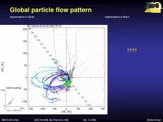
Idea about flow circulationvector presentation The case of backswept flow (BSF) is a small scale radial flow
Methods to determine • Experimental method used - the contact electrodiffusion probe a microsensor inserted onto the particle surface (of 1mm diameter) and Fe-electrolyte. • Mathematical method used – Computational flow modeling CFD Principles
Electrodifusion method for model validation • The external flow velocity gradient was evaluated by a contact electrochemical probe (sensor 1mm, Ae,Le). The local diffusion limited current Id, of ferric cyanide ion reduction (Deff), at the probe interface was measured, as related to solid-liquid mass transfer (ks) that occured in the boundary layer.
Exp. method validation results Measurement vs. reference friction drag coefficients * Shames (1997), ** Clift et al. (1989) *** Chhabra and Richardson (2001)
CFD characterization • FLUENT13 • Unstructured mesh for complex shape wit approx. 1 mln cells • tetrahedral mesh for the volumes immediately surrounding the impeller blades and thedisk. • hexahedral mesh for the tank. • The MRF approach and SKE turbulence model coupled with Eu-Eu formulation of 2 phase flow • Conformal grid interface between the inner rotating frame and and the outer cylindrical vessel • Convergence improved by a segregation implicit solution approach and SIMPLEC pressure-velocity coupling • Up to 50 000 iterations within 500 timesteps 0.01s
Mesh refinement degrees down to <0.05 mm linear dimension
Basic equations The hydrodynamic stress was determined from shear rate and the constitutive equation of the fluid (a non-Newtonian power law one).
Modeling validation studies • computed shear rate in water: • 10 500 s-1–11 100 s-1 • Measured shear rate =10 700 s-1.
Validation by performance parameters Comparison of performance parameters • Experimental power number Po~1 ± 0.2 • CFD values obtained • in water at N=600 rpm – Po=1.20; • in glycerol 56 mPa.s at N=900 rpm – Po=1.21; • in xanthan gum (n=0.5, K=1 mPa.sn), N=600 rpm Po=1.14; • in xanthan gum (n=0.23, K=2.2 mPa.sn). N=900rpm Po=1.19
Validation experiments in CFD Comparison of exp. versus CFD-predicted values of shear
Answers of three basic issues have been sought: • Assuming that cell fragmentation is proportional to the relative speed of approach, the wall shear rate was the representative parameter of interest and answers of three basic issues have been sought: • What level of particle wall shear rate (Sw) is generated by the impeller-imposed flow? • What and at what extent is the effect of gas presence? • Within the practical range of rotational velocity, could the flow produce wall shear stress (w) valuescritical for processing of animal cells or mycelia cultures?
Presentation of results The flow field vessel dimension and body dimension were analysed (2) The body dimension by radial coordinates 3-D solid body diagrams (1) The vessel dimension by planes
Fig. 1 The vessel dimension Increasing deviation from Newtonian flow from left to right(shear rate in s-1) decreases flow mobility 2-D contours of velocity magnitude (in m/s) of plane x=y at N=750 rpm and VG=0 corresponding to various flow behavior, e.g. n=0.78 (K=0.02Pa.sn), n=0.34 (K=0.55Pa.sn), and n=0.34 (K=4.6 Pa.sn), respectively.
RESULTS Fig. 2 Comparison liquid velocity at low consistency 750 rpm 0.02/0.78 m/s Liq Low velocity region extended ungassed gassed
RESULTS Comparison liquid velocity at high consistency (0.1mPas) Fig. 3 m/s gas presence no gas Liq Gas Liq Low velocity region unchanged
RESULTS Fig. 4 V-Contours magnified Velocity, 750rpm_n=0.78, K=0.02Pa.s No gas vs. gassed liq velocity Velocity, 750rpm_n=0.78, K=0.1Pa.s gas velelocity no gas vs. gassed
RESULTS Fig. 5 Pressure field near particle 750 rpm_0.1_No Gas No Gas 750 rpm_0.1_with Gas Aeration Pressure drop increases at particle rear
RESULTS 2-D contour plots of fluid shear deformation rate (in s-1) The bed dimension for BS Flow! Fig. 6 Fluid shear Increasing deviation from Newtonian flow from left to right(shear rate in s-1) decreases mobility of flow.
RESULTS The effect of gas presence Fig. 8 FLUID SHEAR NEAR PARTICLE np gas 750rpm_n=0.78, K=0.02Pa.s gas decrease unchanged np gas 750rpm_n=0.78, K=0.1Pa.s gas presence
RESULTS Comparison Vector plots NO GAS vs. GASSING Fig. 9 The vector plots related to volume-averaged single phase flow indicate separation conditions (2MV_750rpm_n=0.78_K=0.1Pa.s) likely to enhance flow separation at the particle rear.
Discussion Referring to the results at vessel dimension: ● Low velocity zones at particle rear. ● Accompanied by low pressure zones formed. ● Separation is likely to occur. ● In gas presence, velocity redistribution is observed. ● Gas pockets in low-pressure zones are formed that are likely to shield part of the particle surface.
APPLICATION FLOWING MATTER Wall shear at particles in colloidal dispersions The particle dimension for BSF! The effect of gas Fig. 10 Particle Side View The high stress zone is seen by the side stream Shear depression due to gas-decele- rated liquid is observed in both cases
RESULTS The particle dimension for BSF! The effect of gas Fig. 11 Particle Rear View The ‘lowest stress’ zone coincides with the low pressure gas-domi- nated zone at the particle rear In gas presence, decrease of the low shear zone size observed in the diluted dispersion
Fig. 12a RESULTS The effect of gas presence on shear Shear decrease determined The effect at low consistency Fig. 10A
Fig. 12b RESULTS The effect of gas presence on shear The effect at high consistency Shear unchanged or shear increase determined Fig. 10B
APPLICATION FLOWING MATTER Tracing cell demege in mycelia and cell culture bioprocessing Fig. 13 The effect of consistency! Max shear on particle 2-fold decrease
Discussion Referring to the effects seen at body dimension : Evidence for areas of critical performance - # The high stress zone is expected by the side stream, while the lowest stress zone in gas presence coincides with the low pressure gas filled zone at the particle rear. This is valid strongly for the case of low consistency (K=0.02 Pasn). # The case of high consistency (0.1Pa.sn) shows a slight decrease in shear (something like 1200 to 1160 s-1, due to only the density effect of the gas-liquid mixture. In cases due to variation of gas spread, the shear in gas presence may increase.
Area-averaged parameters While the results so far explain the effect, the magnitude of the effect itself is the important result for practice: What are the ranges of shear stress and How do they conform to reported criteria for cell fragmentation? The results are seen in Table 2
Table 2Average wall shear stress and the effect of gassing area-averaged values Shear stress should not exceed 2-3 N/m2 for animal cultures and 80 N/m2 for mycelia (Ludwig et al., 1994 ) At low and high K, opposite response is revealed
DISCUSSION In order the bioprocessing vessel specified to be acceptable for operation, shear deformation should not exceed shear stress 2-3 N/m2 for animal cultures (Ludwig et al., 1994) and 80 N/m2 for mycelia. Referring to the data of Table 2 related to the impeller discharge area, the presence of gas at consistency rise increases shear up to 30 %; yet The backswept impeller-induced circulation is well within the limits for proper bioprocessgrowth in mycelia cultures However, even at low mixing intensity the critical values of shear stress for animal cells are exceeded.
CONCLUSIONS # The study presents a CFD-based assessment of important flow parameter - an image of shear imposed on particles immersed in complex (non-Newtonian) fluid with engineering application in fermentation and cell culture agitated bioreactors. # The study reveals themaximum impact of flow at the wall of a particle in colloidal dispersion circulated by means of impeller in presence of gas. #Referring to knowledge of critical values reported in the literature, the flow condition results allow to classify practically occurring operational regimes as optional in terms of potentials for cell damage. #Referring to the critical values reported, evidenceisgivenforareas of critical performancein case of primary circulation that imply cell fragmentation in practical cases of cell culture bioprocessing.
References Hanratty, T.J., Campbell, J.A. Measurement of wall shear stress. In: Goldstein, R.J. (Ed.), Fluid Mechanics Measurements. Hemisphere, Washington, 1987. Ludwig, A., Kretzmer, G. and Schügerl, K., Determination of a "critical shear stress level" applied to adherent animal cells. Enzyme Microb. Technol. 14 (1992) 209-913.
Acknowledgement COST Action MP1305 FLOWING MATTER support in delivering this study to specialized audience is acknowledged. Thank you!
APPLICATION FLOWING MATTER Tracing cell demage in mycelia and cell culture bioprocessing Visualized flow impact on shear-sensitive cells = wall shear at particles in colloidal dispersions