207 TEMPORARY SEDIMENT AND EROSION CONTROLS
440 likes | 609 Vues
2013 Construction and Material Specifications Hydraulics and Environmental Summary Gary Angles, Office of Construction Administration. 207 TEMPORARY SEDIMENT AND EROSION CONTROLS. This item has been removed from the 2013 C&MS. Stormwater Controls are included in SS832 .

207 TEMPORARY SEDIMENT AND EROSION CONTROLS
E N D
Presentation Transcript
2013Construction and Material SpecificationsHydraulics and Environmental SummaryGary Angles, Office of Construction Administration
207 TEMPORARY SEDIMENT AND EROSION CONTROLS • This item has been removed from the 2013 C&MS. Stormwater Controls are included in SS832. • Cleaned up references to OHWM in the specs and SCDs • Revised updated MOP • Proposed CGP public notice January 11
Item 601 Slope and Channel Protection • 601.01 - Description • Removed interlock precast concrete blocks and added Articulating Concrete Block Revetment System • 601.04 - Riprap • B. Revised definition for articulating concrete block revetment system and removed interlock precast concrete block. • 601.12 - Tied concrete block mat • Added reference to 712.12 and to install per the manufacturer’s recommendation. • 601.13 - Articulating concrete block revetment system • New material type description. • 601.15 - Basis of payment • Added: Articulating Concrete Block Revetment System. • Removed: Water Quantity Swale Aggregate, Tied Concrete Block Mat for Water Quantity Swale and Interlock Concrete Blocks.
The Articulating Concrete Block Revetment System is a segmented mat used for hard armoring along stream banks, lakes and major channels. Articulating Concrete Block Revetment System Tied Concrete Block Mat is a rolled product used at bridge ends and underdrain outlets. Tied Concrete Block Mat
Item 602 MASONRY • 602.02 - Materials • Removed reference to 203.02R and added 703.16.C granular material types. • 602.03 - Construction requirements • 8E. Added section for pre-cast structures for wing walls and headwalls and removed slab footers and cut off walls. • Double PE seal required • More to follow RE: Standard method of measurement
Items 603 and 604 • Removed item 603 and 604. Performance based 611 will replace the 603 and 604. Item 611
Item 605 UNDERDRAINS • 605.02 - Materials • A. Removed Polyvinyl chloride plastic pipe.
Item 651 TOPSOIL STOCKPILED • 651.02 - Construction requirements • 653 reference removed and specific material handling described Item 653 TOPSOIL FURNISHED and PLACED • 653.04 - Method of measurement • The Department will measure compacted Topsoil Furnished and Placed by the number of CY accepted in place.
Item 671 EROSION CONTROL MATS • 671.03 - Construction • A. Removed Type D. • Coconut fiber with biodegradable tissue (no longer manufactured) • C. Removed this entire section • Eliminated mat type not being used. Described Type H mats that were a modified version of type A mats.
Hydraulics, Item 611 SummaryJeffrey Syar, Administrator Office of Hydraulic Engineering
Item 611PIPE CULVERTS, SEWERS, DRAINS, AND DRAINAGE STRUCTURES • This is a Performance Based Specification that encompasses 2010 items: 603, 604 and SS 802. • SS 802 is now item 611.
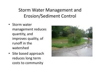
Why Change? • Method based specifications were being faulted when conduit was poorly installed by the Contractor • Resulted in the Department accepting poorly installed conduit or incurring additional costs during construction
Background • 1997 – SS802 optional performance based installation specification included on all projects with 603 and 604.
Background • 2008 SS 802 was revamped with the intent of developing a performance based standard specification • 2009 SS 802 was required on a number of projects state wide in an attempt to pilot the specification. • 2012 Projects that are sold after March 31, 2012 and have any Item 603 or Item 604 work and have a construction cost estimate of 10 million dollars or more. • 2013 Implement C&MS 611 (Page 471)
General Differences • The contractor develops and executes his own installation plan for all conduit and drainage structures. • Requires documented coordination between the material supplier and the installer.
General Differences (cont’) • Conduit and drainage structures require both Installation and Performance Inspection that is tied to payment. • Contractor is required to repair or replace conduits and drainage structures that do not meet the performance requirements. • 611 Substantially expanded the acceptable inspection methods and equipment versus SS 802.
How it works • Contractor selects the drainage component materials allowed by contract (as shown in the plan). • Contractor develops an installation plan appropriate for the materials selected. • Contractor installs, monitors and documents the installation. • Based on contract criteria, the Contractor provides inspection / 3rd party evaluation and certification of Performance.
Conduit • Conduit shown in the plans is designed for hydraulic capacity and durability only • Structural design is performed by the Contractor in coordination with the conduit Manufacturer
Submittals • Shop Drawings • Installation Plan • Construction Inspection Forms • Performance Report
Shop Drawings • Have a Registered Engineer prepare, sign, seal and date all calculations. Second Registered Engineer checks and seals the submittal as well. • Allow at least 15days for the review. • Note: • D load special design reinforced concrete pipe • Concrete precast 3 sided, arches and round sections • Substitutions involving box culverts and or 3 sided, arches and round sections.
Installation Plan • Trench dimensions • Identify locations where the conduit is installed in a • cut installation • fill installation • Type of bedding and backfill material with lift thickness • Compaction density and equipment proposed for bedding and backfill • Identify the starting location for each run of conduit • Maximum allowable joint gap between conduit sections • Other installation details as necessary
Installation Plan (cont.) • Provide written confirmation from the conduit manufacturer that the pipe material and strength supplied are appropriate for the material and density requirements described in the installation plan regarding backfill and bedding as well as height of cover. This confirmation by the conduit manufacturer will not relieve the Contractor of the responsibility for obtaining the required results.
Construction Inspection Forms • Perform work only in the presence of the Contractor’s representative doing the inspection. Submit construction inspection forms to the Engineer for each run of conduit and each drainage structure. • Form CA-P-1 for conduit • Form CA-P-3 for drainage structures. • “I certify that the information on this form is accurate and all deviations from the current installation plan have been noted.”
Performance Report • Performance report required for each Performance Inspection • Separate report for each change in conduit size or change in material type • Report includes the following: • Project information • Date of inspection • Type and size of conduit • Conduit diameter report from the Manufacturer • Time of video recording • Location – latitude and longitude where conduit crosses centerline of roadway – for culverts • Summary of all defects and locations • Size of Mandrel and how the size was calculated if using Mandrel • Results from crawler mounted camera with laser profiler if using laser profiler
Performance Report • Submit performance report within 5 days of completing a performance inspection to the Project Engineer
Performance Inspection • Notify the Engineer at least five workdays before conducting a performance inspection. • A performance inspection is not required for projects that meet all of the following: • All conduit is Type C (Sewers not under pavement) • Conduit plan quantities are less than 100 feet • All conduit has less than 16 feet of maximum fill height
Performance Inspection (Cont’) • Inspection is performed between 30-90 days after: the • completion of the finished grade when not below pavement • after the completion of the aggregate base when below pavement. • after completion of conduit correction • Engineer may adjust this time frame if the contract duration will not permit a 30 day waiting period.
Performance Inspection (Cont’) • Inspection required for Conduits and Drainage Structures • Inspection required for any conduit that requires correction • Inspection may be performed by Contractor • Ensure the Project Engineer is present during all performance inspection activities • Project Engineer must be notified at least 5 workdays before conducting a performance inspection
Manual or Remote Inspection • Either Manual or remote inspection are required to measure cracks, deflections, and joint gaps in conduit. • Conduits with a rise 48 inches and greater Manual Inspection • Conduits with a rise of 36 to 48 inches Manual or Remote Inspection • Conduits with a rise of 12 to 36 inches Remote Inspection • Drainage Structures are inspected Manually
Manual Inspection • Manual inspections require entering the conduit or drainage structure to record video and to make measurements - coordinate confined space access per OSHA requirements.
Remote Inspection • Use a crawler mounted camera to record video with the equipment described in Supplemental Specification 902. • Remove all debris from the conduits being inspected according to 107.19. Dewater the conduit if the water level hinders the performance of the equipment.
Conduit Inspection - Flexible Conduit • Evaluate: • If infiltration is observed. • All racking, buckling or denting. • Vertical alignment of conduit –(Ensure there are no vertical sags in the conduit that trap water) • Repair or replace conduit if the joint gap exceeds the tolerance (as described in the installation plan)for a length greater than or equal to 1/3 of the circumference • Repair all coating damage • Repair or replace conduit if deflection > 7.5%.
Conduit Inspection - Rigid Conduits • Evaluate if infiltration is observed • Evaluate if joint gap exceeds the tolerance* for a length less than 1/3 of the circumference • Evaluate vertical alignment of conduit – Ensure there are no vertical sags in the conduit that trap water. Repair or replace conduit if the joint gap exceeds the tolerance* for a length greater than or equal to 1/3 of the circumference • Repair or replace conduit if cracks > 0.10 inch • Repair or replace conduit if spalls or slabbing are observed * Maximum joint gap listed in the installation plan
Conduit Evaluation • Have an independent Registered Engineer evaluate the conduit and any defects as required by AASHTO LRFD Bridge Construction Specifications (Section 26, 27 and 30) with modifications according to this specification. • The independent Registered Engineer cannot be an employee of the Contractor or the conduit manufacturer.
Conduit EvaluationCertification Sign off • “I certify that repairs are not required for the conduit to function as designed and that the conduit meets the design life requirements described in the version of the Department’s Location and Design Manual, Volume 2, Drainage Design, used in the original design.” • “I certify that this repair plan was designed to ensure the repaired conduit will function as designed and will meet the requirements described in the version of the Department’s Location and Design Manual, Volume 2, Drainage Design, used in the original design.”
Drainage Structure Evaluation • Drainage Structure Evaluation. Have an independent Registered Engineer evaluate the drainage structures and any defects listed in the table below. • Certification of Engineer’s finding • repairs are not required …meets the design life • this repair plan was designed to ensure the repaired drainage structure will function as designed…
Surface Settlements • Repair any surface settlement within the trench limits or within 4 feet of a drainage structure. Have an independent Registered Engineer evaluate the conduit according to 611.13 or the drainage structure according to 611.14. Perform all repair work at no additional cost to the Department.
Basis of Payment • Payment for all inspection(s) is included with the contract unit price of the corresponding pay item. • All required repairs, including any settlement problems, must be made prior to acceptance. • Department will not make additional payment for repair work on conduit installed under this specification.
Basis of Payment • The Department will pay for accepted quantities according to the following schedule: • 60% After installation of conduit or drainage structure • 10% After performance inspection is completed • 30% After acceptance of the conduit or drainage structure
SS 902 – Conduit Inspection Equipment • Covers equipment used to inspect conduit • Crawler Mounted Camera • Crawler Mounted Camera with Laser Profiler • Mandrel
SS 811 - CONDUIT AND DRAINAGE STRUCTURES • Method based specification for conduits and drainage structures • Old CMS 603 and 604 combined • Exclusive use for Local Governments only • Not permitted for ODOT let projects • Will be eliminating from ODOT Specifications in January 2015
SS 811 - CONDUIT AND DRAINAGE STRUCTURES • Designer is responsible for furnishing conduit meeting structural, hydraulic and durability design • Refer to archived L&D Vol. 2, for Height of Cover Figures • Refer to SCD DM-1.4 for Conduit Installation
SS 940 - 14 FT TO 20 FT PRECAST REINFORCED CONCRETE BOX CULVERTS • Large Reinforced Concrete Boxes do not require special designs like 2010 specifications • Via Boiler Plate (SS 800), SS 940 can be used for reinforced boxes with spans 14-20 feet
Questions • Jeffrey.Syar@dot.state.oh.us • 614-275-1373