Download

1 / 48
490 likes | 752 Vues
Outdoor Site Survey. MDU, Campus Networks, WISP. Learning Objectives. Upon successful completion of this lesson, you will be able to:. Discuss the keys to ensuring a successful site survey. State the procedures for conducting a site survey.

E N D
Outdoor Site Survey MDU, Campus Networks, WISP
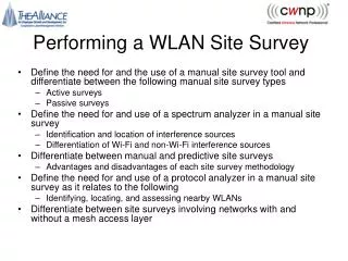
Learning Objectives Upon successful completion of this lesson, you will be able to: • Discuss the keys to ensuring a successful site survey. • State the procedures for conducting a site survey. • Discuss the issues regarding improper antenna co-location. • State the purpose of using a spectrum analyzer for conducting a site survey and using the built-in one. • Describe how Microwave Ovens and DS Systems affect RF Propagation. • Describe the proper ways of mitigating in-band interference.
Site Survey Basics • The performance of an outdoor Site Survey is “VITAL” to the success of the intended implementation. • Keys to ensuring a successful site survey process: • Determine the type of network needed. • Choose locations carefully. • Use proper tools. • Conduct a thorough feasibility study. • Implement effective test plan. • Document site survey results.
Determine System • BWA • Point-to-Point • Point-to-Multi-Point • Campus/MDU What type of network is to be designed?
Choose Locations • Based on business plan • Accessibility • Demographics • Locations could be: • Towers • Tall Buildings
Feasibility Study • Topographic study & GPS plotting • LOS Mapping • Preliminary site analysis • Preliminary design
Test Plan • What is a test plan? • A test plan is a developed method by which the following is accomplished: • Development of RF testing procedures. • How to simulate the installations • Set standards for testing methods. • Define acceptable results for testing. • Document…Document…Document!!!!!!
RF Site Survey • Geographical Data • Distance between sites • Clear path between sites • Weather • Antennas Location • Height of Antenna at each site • Distance between Transceiver & Antenna • Interference? • What other antennas are at or near the location? • What frequencies are they at what power? • Conduct spectrum analysis • Measuring the RSSI in both directions
RF Site Survey • Determine Site Locations (LAT/LONG) • Use GPS • Use Mapping Software • Document site locations, issues, and comments • Use digital cameras with documentation
RF Site Survey • Determining short distance LOS • Visually from point of proposed antenna • Determine obstruction heights • Determine Fresnel Zone clearance needed • Determine Antenna mounting height
Site Survey Tools • Tools Recommended for Outdoor Site Surveys: • Appropriate wireless testing equipment (BA Radios, Spectrum Analyzer, etc…) • GPS • Lensetic compass • Binoculars • Remote power • Ladder or lift (if necessary) • Portable power supply – xPower300 • Antenna attachment hardware • Appropriate software (mapping, topo, etc…) • Laptop with traffic generation software
Deployment for Site Survey • Implement test plan • Gather implementation data • Record results
Free Software • There are two different software packages that can be found out on the Internet. • Both will show basic fresnel zone clearance between two points on Earth. • Both can show a “profile” view of the terrain and the fresnel zone together. • Both are free. • RadioMobile • http://www.cplus.org/rmw/english1.html and • MicroDEM • http://www.usna.edu/Users/oceano/pguth/website/microdem.htm
MicroDEM • MICRODEM is a microcomputer mapping program written by Professor Peter Guth of the Oceanography Department, U.S. Naval Academy. It requires a 32 bit version of Windows (NT/2000 or 95/98/ME). • Handles many different file formats: DTED, DEM, TOPO30, SDTS • MICRODEM displays and merges • digital elevation models • satellite imagery • scanned maps • vector map data • GIS databases • It can overlay satellite image on top of terrain data. But it doesn’t modify elevation data based on Land Use (foliage, industrial, residential etc).
Radio Mobile • Radio Mobile is a complete path analysis and propagation program written by a Canadian HAM radio operator. It requires a 32 bit version of Windows (NT/2000 or 95/98/ME). • It handles elevation data in DTED and GTOPO30 format only. • You will have to convert the DEM files from USGS into DTED files (A free converter exists). • Like MicroDEM, a background satellite photo can be overlaid on the terrain data. But it doesn’t modify elevation data based on Land Use (foliage, industrial, residential etc).
Free Data • The data files, also called “DEM” files, are also free: • U.S. Geological Survey (USGS) • Covers US in two datasets: • 1:24,000 SCALE = ? / File Format: SDTS • 1:250,000 SCALE = 3 arc sec. = 100m. / File Format: DEM • http://edc.usgs.gov/geodata/ • National Imagery and Mapping Agency (NIMA) • Covers 50% of the globe • Format: DTED (Level 0) = non-classified data • http://geoengine.nima.mil/ • 1 sec. arc data for Radio Mobile • ftp://edcsgs9.cr.usgs.gov/pub/data/srtm/united_states_1arcsec/1arcsec/
Radio Planning • MapInfo Application • Runs on Win95, Win98 or WinNT • Inputs from User • 3D geographical maps, up to1m resolution, including buildings (MapInfo compatible) • Radio parameters (frequencies, power,…) • Antenna parameters (gain, radiation pattern, direction, …) • Site parameters (Base Stations locations, clients locations, …) • Capacity requirements (data only, data and voice, traffic parameters, …) • Output from the Radio Planning Tool • RSSI coverage =>available capacity • User affiliation to Base Stations
Why use a Spectrum Analyzer • The Spectrum Analyzer allows us to “peek” into the frequency band in which our radios operate. • It tells us if there are other RF transmissions besides the intended wireless link. • If used properly the Spectrum Analyzer can tell us: • What type of source (DSSS, FHSS, Microwave Oven, Cordless Phone, etc). • In what direction is the source, from your tower. • Location of source can be found if enough data is collected from at least 2 other survey locations. (Triangulation). • Whether or not the Carrier Sense Level should be adjusted (FH). • Whether or not the Channel should be changed (DS).
Examples of Interference, cont. • DSSS can look like this: Channel 6 Use the “Peak” function to find the center of DS spectra. 2.437 GHz
Mitigating Interference • Now we know the “interference” is a DS radio on Channel 6, we can try to use Channels 1 and 11 instead. • Or, change to Horizontal Polarization for the antennas that are affected by the interference. In this instance, it is necessary to change BOTH sides. • Sometimes a higher gain unidirectional antenna helps when the interference is from the side. This has the effect of lowering the gain for the side lobes and increasing the received signal strength (S/N ratio ). Main lobe Interference source Side lobe Reduced gain
Mitigating Interference, cont. • If the interference is a FH radio, then: • Change to Horizontal Polarization for the antennas that are affected by the interference. In this instance, it is necessary to change BOTH sides. • Try several hopping sequences. • Use a higher gain antenna to reduce gain on the side lobes. • Try to re-position antennas in such a way as to use some part of building to block the interference.
Further Detection • If there is a definitive signal that can be seen in the first analysis, it maybe a good idea to get a bearing for this signal. The bearing (heading) for the signal could help in choosing a new antenna for the location. • Instead of MAX HOLD, use the standard sweep mode. • Scan the horizon in the general direction of the interference. • Try to obtain the strongest signal on the Spectrum Analyzer. • Use your compass with the UNI-9 to determine the bearing for this signal and write it down. • Repeat this for other strong signals you have detected.
What to do with the bearing data • You may be able to select an antenna that has a “null” or low point in the gain at that angle. • You need the azimuth of the current antenna. This is the direction (in degrees) that the antenna is pointing. • You need a polar plot of the proposed new antenna. • You need the bearing of the interference source. 0* Bearing angle Azimuth (15°) N Interference source (315°) Side lobes Null
Getting Started for 900 MHz • How do I know if there is potential 900 MHz channel interference or background noise in my area? • How do I find the best clear channels for my 900 MHz system? • How do I know which antenna to use at my AU location? • How can I safely co-locate multiple AU units in same operating area? • How do I commission my units with best hopping sequence?
Determining Available Clear Channels Procedure • Spectrum Sweep All AU Sites / Minimum 2 SU Sites • Spectrum Analysis All Spectrum Sweep Captures • All spectrum sweep and analysis steps MUST be done in exact order ! • Reference the BreezeACCESS Spectrum Analyzer User Guide for step by step instruction • http://www.alvarion-usa.com
Determining Available Clear Channels Process Steps (AU / SU ) • Mount antenna in exact position and direction (V / H-Pol) • Load Special Spectrum Sweep Firmware on AU/SU unit • Connect to AU / SU via Terminal Session / SNMP • Sweep Full 900 MHz spectrum (903-927) S - Show Flexible Hopping Parameters Channel Spacing : 2 MHz * Scrambling Sequence Mode : Enhanced Sub-Bands, by Carriers (MHz) : 903-927 Carriers (Center Frequency) to be used (MHz) : 904.000, 906.000, 908.000, 910.000, 912.000, 914.000, 916.000, 918.000, 920.000, 922.000, 924.000, 926.000 CURRENT hopping sequence (MHz) : 904, 906, 908, 910, 912, 914, 916, 918, 920, 922, 924, 926 *Actual frequency used 1 MHz 903-927 (includes guard bands)
Process Steps – cont. • Install BreezeACCESS 900 MHz Spectrum Analyzer Application Tool • Three Modes of Operation (see next slide) Offline Mode – display previously saved spectrum sweep results. Serial Mode – provides real-time data capture for full spectrum sweep vial serial port connection. SNMP Mode – provides real-time data capture for full spectrum sweep via remote SNMP management session.
Using Spectrum Analyzer Application Offline Mode – Analysis and Printing From the application tool bar choose File\Open and select achieved file. It is recommended that every spectrum sweep, including different combinations of the AU or SU antenna mount orientation be saved as a unique file with some logical name that refers to the test setup (e.g. CX-NE-Tower- Vertical-Pol.txt).
Using Spectrum Analyzer Application – cont. Serial Mode – Actual Mode of Operation (Setup) • Configure Comm. Port; Baud Rate for serial PC • Administrator Password MUST match SU • Configure Logout Timer appropriately • Run spectrum sweep a minimum 10 mn per location • Clear spectrum sweep results for new sweep capture or Save sweep to append to previous sweep captures • Version of Spectrum Analyzer Tool shown in (HELP) • Exit terminal emulation program (no other application should use the COM port. It is recommended to try both vertical and horizontal antenna Configuration to determine clear channel communication. In this case you must clear spectrum results.
Spectrum Analyzer Application Steps • Analyzer Utility automatically recognizes if special Spectrum Sweep firmware is in shadow memory; prompts for software boot • Higher number of “scanned frequencies” equals higher Minimum Refresh Time • New Settings are “saved” automatically upon exiting utility • Start / Stop “spectrum sweep” via dialog button • Save “capture” for analysis in Offline Mode • Upon new sweep you will be prompted to decide whether to import the data collected previously or to restart the data collection.
Determining Available Clear Channels Interpreting Spectrum Sweep Data
Determining Clear Channels Determining the best frequencies to use should be done by correlating the results of the two graphs by looking at the lowest number of “Average dBm” Upper Red with “Average False alarms” Lower Red and lowest “Max dBm” Upper Orange with “Max False Alarms” Lower Orange. In the example graph shown in previous slide the frequencies matching these criteria are from 908-910. This example shows heavy RF spectrum interference is in the area, and it is likely that the performance will be poor. It can be easily seen that the upper frequency range is heavily polluted by theproximity of a Pager tower. • Spectrum Analyzer mode mode equal 1 MHz channel vs. normal mode equal 2 MHz channel. Important for analysis and channel selection. • Operate at maximum clear channel for best diversity in frequency and time domain. • The higher the number of channels, the lower will be the effect on performance if a previously unidentified interferer will emerge.
Example 1 – cont. In the previous slide example the frequencies matching the selection criteria are from 903 to 905 and 910 to 918. Note the arrows on the graph to highlight the clear channel multiple frequency range configuration. The actual center frequencies that will be used in this configuration are 904, 911, 913, 915 and 917.
Example 2 – cont. In the example in previous slide the frequencies matching the criteria are 908, 909, 916, 917 and 922. Note the arrows on the graph to highlight the clear channel multiple frequency range configuration. Keeping in mind that the BreezeACCESS 900 system operates in 2 MHz channel spacing in normal mode, you would set your AU and SU Flexible Hopping Definition hop sequence to 909, 917, and 922, expecting clear channel performance under minimal amounts of 900 MHz signal interference.
Hopping Sequence Configuration in BreezeACCESS 900 MHz Units Once the clear channels are determined, use the Flexible Hopping Definition option to define the correct hopping frequencies in the BreezeACCESS 900 system components. For more information on actual configuration and menu functionality refer to Appendix D – Configuring Hopping Frequencies and Operational Frequencies in the BreezeACCESS 900 System Manual. Depending on the number of frequencies chosen via previous steps, it is important to select the proper Scrambling Definition mode: • For up to 6 frequencies – select Standard Scrambling Mode • For more than 6 frequencies – select Enhanced Scrambling Mode In this case, a Spanning Factor must be defined in the AU. Select a mid- range Spanning Factor value out of those that are available for the appropriate total number of channels. For example, if you have a total number of 7 channels, the appropriate Spanning Factor selection will be either 3 or 4.
Spectrum Analysis in LB • Turn on radio • If number in the SNADR number is anything other than zero you have interference • If you have a problem link • Log into remote radio • Uncheck enable radio • Click TEST • This will disable transmitter on that side for 5 minutes • Then check SNADR on radio you are behind.
Summary In This Lesson, We Discussed… • Site Survey Procedures • Radio Path Analysis Software • Antenna Co-location Issues • Using a Spectrum Analyzer to Conduct a Site Survey • Ways to Overcome Interference