Download

1 / 24
240 likes | 397 Vues
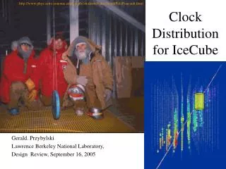
Research of long distance clock distribution system. Université Libre de Bruxelles (IIHE) Yifan Yang , Kael Hanson, Aongus Ó Murchadha, Thomas Meures, Michael Korntheuer. OVERVIEW. Askaryan Radio Array background

E N D
Research of long distance clock distribution system Université Libre de Bruxelles (IIHE) Yifan Yang, Kael Hanson, Aongus Ó Murchadha, Thomas Meures, Michael Korntheuer
OVERVIEW • Askaryan Radio Array background • Clock distribution over optical fiber based on low cost FPGA and jitter cleaner. • Fixed latency link implementation. • Conclusion and future plan. SEP 2012 TWEPP
Askaryan Radio Array background • Clock distribution over optical fiber based on low cost FPGA and jitter cleaner. • Fixed latency link implementation. • Conclusion and future plan. SEP 2012 TWEPP
Askaryan Radio Array 37 stations Spacing: 2 km Depth under ice surface: 200 m Surface coverage: ~160 km2 Ice thickness below: ~3000 m Each station: 16 + 4 sub-firn antennas (sensitive between 250 and 800 MHz):8 vertically polarized8 horizontally polarized 4 calibration pulsers (v-pol + h-pol) X surface antennas SEP 2012 TWEPP
Askaryan Radio Array • Current ARA uses analog optical fiber • Easy, COTS (commercial off-the-shelf) item • 1 antenna = 1 fiber => 4 fibers per hole • slightly high power draw • price > 10 kEUR per station • 4 ADC board on surface controlled by single processor board • Digital system • Custom designed • 4 antenna =1 fiber => 1 fiber per hole • Half the price • Extended communication system • 1 ADC board downhole controlled by one FPGA board • 50 ps skew stability is required in one station • 800Mbps data rate SEP 2012 TWEPP
Askaryan Radio Array background • Clock distribution over optical fiber based on low cost FPGA and jitter cleaner. • Fixed latency link implementation. • Conclusion and future plan. SEP 2012 TWEPP
Clock embedded in data • self-clocking signal SEP 2012 TWEPP
GTP To SFP From SFP Recovered clock is synchronized with transfer clock but with larger jitter SEP 2012 TWEPP
SI5368 Footprint compatible Interface compatible with on-surface processor board Generates any frequency from 2 kHz to 945 MHz Ultra-low jitter clock outputs with jitter generation as low as 300 fs rms (50 kHz–80 MHz) Integrated loop filter with selectable loop bandwidth SEP 2012 TWEPP
Evaluation board and measurement setting After switching to recovered clock, a synchronized link is established System clock IRS2 Control module Spartan 6 lx45t with 4 GTPs SI5368 SEP 2012 TWEPP
Clock and data measurements SEP 2012 TWEPP
Latency measurements Before clock switching After clock switching SEP 2012 TWEPP
Clock skew measurement SEP 2012 TWEPP
Askaryan Radio Array background • Clock distribution over optical fiber based on low cost FPGA and jitter cleaner. • Fixed latency link implementation. • Conclusion and future plan. SEP 2012 TWEPP
Latency uncertain from GTP SEP 2012 TWEPP
Latency uncertain from GTP SEP 2012 TWEPP
Latency uncertain from jitter cleaner System clock IRS2 Control module Fixed phase difference between input and output of the jitter cleaner is also needed to establish a fixed latency link. Cdce62005 and LMK03200 both are used in new evaluation board. SEP 2012 TWEPP
New evaluation board and measurement setting Cdce62005(fixed delay) Lmk03200(0 delay) Spartan 6 lx45t with 4 GTPs SEP 2012 TWEPP
Clock skew measurement SEP 2012 TWEPP
Askaryan Radio Array background • Clock distribution over optical fiber based on low cost FPGA and jitter cleaner. • Fixed latency link implementation. • Conclusion and future plan. SEP 2012 TWEPP
Conclusion and future plan • Achieved: • Clock distribution over optical fiber • 50ps skew stability achieved • Latency of the link is kept in a certain range after power cycle on both direction • Things to do: • Long term, long distance, low temperature experiments • Automatic calibration • Remotely firmware upgrade • System optimum SEP 2012 TWEPP
Thank you! SEP 2012 TWEPP
backup SEP 2012 TWEPP
Clock separate with data transfer 250 meters standard cat5 cable SEP 2012 TWEPP