8051 Interrupts
8051 Interrupts. Interrupts Programming. An interrupt is an external or internal event that interrupts the microcontroller to inform it that a device needs its service. Interrupts vs. Polling A single microcontroller can serve several devices. There are two ways to do that:


8051 Interrupts
E N D
Presentation Transcript
8051 Interrupts
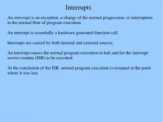
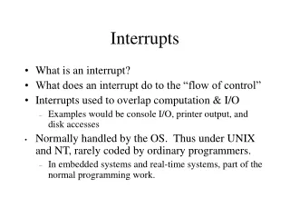
Interrupts Programming • An interrupt is an external or internal event that interrupts the microcontroller to inform it that a device needs its service. Interrupts vs. Polling • A single microcontroller can serve several devices. • There are two ways to do that: • interrupts • polling. • The program which is associated with the interrupt is called the interrupt service routine (ISR) or interrupt handler.
Steps in executing an interrupt • Finish current instruction and saves the PC on stack. • Jumps to a fixed location in memory depend on type of interrupt • Starts to execute the interrupt service routine until RETI (return from interrupt) • Upon executing the RETI the microcontroller returns to the place where it was interrupted. Getpop PC from stack
Interrupt Sources • Original 8051 has 6 sources of interrupts • Reset • Timer 0 overflow • Timer 1 overflow • External Interrupt 0 • External Interrupt 1 • Serial Port events buffer full, buffer empty, etc) • Enhanced version has 22 sources • More timers, programmable counter array, ADC, more external interrupts, another serial port (UART)
Interrupt Vectors Each interrupt has a specific place in code memory where program execution (interrupt service routine) begins. External Interrupt 0: 0003h Timer 0 overflow: 000Bh External Interrupt 1: 0013h Timer 1 overflow: 001Bh Serial : 0023h Timer 2 overflow(8052+) 002bh Note: that there are only 8 memory locations between vectors.
ISRs and Main Program in 8051 ORG 00H SJMP main ORG 03H ljmp int0sr ORG 0BH ljmp t0sr ORG 13H ljmp int1sr ORG 1BH ljmp t1sr ORG 23H ljmp serialsr ORG 30H main: … END
Interrupt Enable (IE) register • All interrupt are disabled after reset • We can enable and disable them by IE
Enabling and disabling an interrupt • by bit operation • Recommended in the middle of program • SETB EA ;Enable All • SETB ET0 ;Enable Timer0 over flow • SETB ET1 ;Enable Timer1 over flow • SETB EX0 ;Enable INT0 • SETB EX1 ;Enable INT1 • SETB ES ;Enable Serial port • by mov instruction • Recommended in the first of program • MOV IE, #10010110B SETB IE.7 SETB IE.1 SETB IE.3 SETB IE.0 SETB IE.2SETB IE.4
Interrupt Priorities • What if two interrupt sources interrupt at the same time? • The interrupt with the highest PRIORITY gets serviced first. • All interrupts have a power on default priority order. • External interrupt 0 (INT0) • Timer interrupt0 (TF0) • External interrupt 1 (INT1) • Timer interrupt1 (TF1) • Serial communication (RI+TI) • Priority can also be set to “high” or “low” by IP reg.
--- --- PT2 PS PT1 PX1 PT0 PX0 Interrupt Priorities (IP) Register IP.7: reserved IP.6: reserved IP.5: timer 2 interrupt priority bit(8052 only) IP.4: serial port interrupt priority bit IP.3: timer 1 interrupt priority bit IP.2: external interrupt 1 priority bit IP.1: timer 0 interrupt priority bit IP.0: external interrupt 0 priority bit
--- --- PT2 PS PT1 PX1 PT0 PX0 Interrupt Priorities Example • MOV IP , #00000100B or SETB IP.2 gives priority order • Int1 • Int0 • Timer0 • Timer1 • Serial • MOV IP , #00001100B gives priority order • Int1 • Timer1 • Int0 • Timer0 • Serial
--- --- PT2 PS PT1 PX1 PT0 PX0 Interrupt inside an interrupt • A high-priority interrupt can interrupt a low-priority interrupt • All interrupt are latched internally • Low-priority interrupt wait until 8051 has finished servicing the high-priority interrupt
Timer interrupt Example1 • A 10khz square wave with 50% duty cycle XTAL = 12MHz ORG 0 ;Reset entry point LJMP MAIN ;Jump above interrupt ORG 000BH ;Timer 0 interrupt vector T0ISR:CPL P1.0 ;Toggle port bit RETI ;Return from ISR to Main program ORG 0030H ;Main Program entry point MAIN: MOV TMOD,#02H ;Timer 0, mode 2 MOV TH0,#-50 ;50 us delay SETB TR0 ;Start timer MOV IE,#82H ;Enable timer 0 interrupt SJMP $ ;Do nothing just wait END
8051 143s 71s P1.7 2ms 1ms P1.6 Timer0 & Timer1 Interrupt Example Write a program using interrupts to simultaneously create 7 kHz and 500 Hz square waves on P1.7 and P1.6. XTAL = 12MHz
8051 143s 71s P1.7 2ms 1ms P1.6 Solution ORG 0 LJMP MAIN ORG 000BH LJMP T0ISR ORG 001BH LJMP T1ISR ORG 0030H MAIN: MOV TMOD,#12H MOV IE,#8AH MOV TH0,#-71 MOV TH1,#0fcH MOV TL1,#18H SETB TR1 SETB TR0 SJMP $ T0ISR: CPL P1.7 RETI T1ISR: CLR TR1 MOV TH1,#0fcH MOV TL1,#18H SETB TR1 CPL P1.6 RETI END
Timer ISR • Notice that • There is no need for a “CLR TFx” instruction in timer ISR • 8051 clears the TF internally upon jumping to ISR • Notice that • We must reload timer in mode 1 • There is no need on mode 2 (timer auto reload)
External hardware interrupts • The 8051 has 2 external interrupts • P3.2 INT0 PIN12 • P3.3 INT1 PIN13 • The interrupt vector table locations are 0003h and 0013h for INT0 and INT1 • There are two activation levels • 1. Negative edge triggered • 2. Low level triggered
Minimum duration required for external interrupt Negative Edge triggered interrupt (XTAL =11.0592) Low level triggered interrupt (XTAL =11.0592)
External interrupt type control (MSB) (LSB) TF1 TR1 TF0 TR0 IE1 IT1 IE0 IT0 Timer 1 Timer0 for Interrupt • By low nibble of Timer control register TCON • IE0 (IE1): External interrupt 0(1) edge flag. • IE = 1 when –ve edge detected at int input. • Does not affected by -ve edge at the int input. • CPU clears IE when RETI executed. • does not latch low-level triggered interrupt • IT0(IT1): interrupt 0 (1) type control bit. • Set/cleared by software • IT=1 -ve edge trigger • IT=0 low-level trigger
External hardware interrupts IEx is external interrupt x flag. Set by CPU when H to L edge at INTx and cleared by CPU when the interrupt is processed.
External interrupt Example ORG 0000H LJMP MAIN ORG 0013H sjmp t1isr ORG 30H t1isr: SETB P1.1 MOV R0,#200 WAIT: DJNZ R0,WAIT CLR P1.1 RETI MAIN: SETB IT1 ;on negative edge of INT1 MOV IE,#10000100B ;enable external INT1 WAIT2: SJMP WAIT2 ;same as instruction sjmp $ END
Serial Ports with Interrupts • General Case • 8051 is in full duplex mode, I.e. receives and transmits data continuously • Both Transmit and Receive is interrupt driven • Write the ISR for Sport such that • ISR must first check which one of RI and TI raised the Sport interrupt • If RI is set, then read data from SBUF to a safe place and • clear RI • If TI is set, then copy the next character to be transmitted into SBUF and clear TI.
Example : Simple case 8051 gets data from P1 and sends it to P2 continuously while receiving data from Serial port and Serial port data is to be displayed on P0.