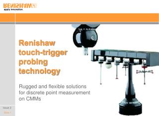
Renishaw scanning technology
Renishaw scanning technology. Renishaw’s innovative approach to scanning system design compared with conventional solutions. Issue 2. technology. Questions to ask your metrology system supplier. Do my measurement applications require a scanning solution? how many need to be scanned?


Renishaw scanning technology
E N D
Presentation Transcript
Renishaw scanning technology Renishaw’s innovative approach to scanning system design compared with conventional solutions Issue 2 technology
Questions to ask your metrology system supplier • Do my measurement applications require a scanning solution? • how many need to be scanned? • how many need discrete point measurement? • If I need to scan, what is the performance of the system? • scanning accuracy at high speeds • total measurement cycle time, including stylus changes • If I also need to measure discrete points, how fast can I do this?
Questions to ask your metrology system supplier • Will I benefit from the flexibility of an articulating head • access to the component • sensor and stylus changing • What are the lifetime costs? • purchase price • what are the likely failure modes and what protection is provided? • repair / replacement costs and speed of service
Probing applications - factors Manufacturers need a range of measurement solutions. Why? • machining processes have different levels of stability: • stable form : • therefore control size and position • discrete point measurement • form variation significant : • thereforeform must be measured and controlled • scanning
Probing applications - factors Manufacturers need a range of measurement solutions. Why? • Features have different functions: • for clearance or location • form is not important • Discrete point measurement • for functional fits • form is critical and must be controlled • Scanning Measured values Best fit circle Maximum inscribed (functional fit) circle
Scanning Typical scanning routines to measure form Scanning provides much more information about the form of a feature than discrete point measurement Spiral scanning of a cylinder bore gathers data about feature size, position, orientation and form
Renishaw scanning - our objectives • speed and accuracy • design sensors with high dynamic response to provide high accuracy data at high speed • accurate through use of sophisticated probe calibration • match styli materials to applications for best results • flexibility • probe changing • stylus changing • articulation • cost effectiveness • innovative hardware and scanning techniques reduce complexity • robust designs and responsive service for lower lifetime costs
Renishaw scanning systems Active and passive scanning probe design Renishaw scanning sensor design Performance styli for scanning Articulating heads Probe and stylus changing
Simplicity • no motor drives • no locking mechanism • no tare system • no electromagnets • no electronic damping • Complexity • 3 force generators • 3 dampers • LVDTs mounted on stacked axes Active or passive sensors? Passive sensors Active sensors • Design • active sensors are large, heavy and complex • passive sensors are small and relatively simple
Passive sensors Simple, compact mechanism • no motor drives • no locking mechanism • no tare system • no electromagnets • no electronic damping • springs generate contact force • force varies with deflection Typical scanning deflection Force Deflection
Active sensors Complex, larger mechanism • force generators in each axis • force is modulated in probe • not constant at stylus tip* • deflection varies as necessary • longer axis travels Displacement sensor Axis drive force generator Force Controlled force range Deflection * see next slide
Active sensors Errors in force modulation at stylus tip • force is modulated at each stacked axis • mechanism & stylus mass, plus stylus stiffness connect force generator to stylus tip • errors that lead to uncontrolled stylus force: • inertial acceleration of stylus mass • error in estimating probe acceleration (d2xp/dt2) • error in estimating probe velocity (dxp/dt) • error in estimating quill acceleration (d2xq/dt2) • force feedback error (eFp) Force Fp controlled here What matters is force Fs here Fp cp Quill Probe mechanism mass Stylus mass Fs kp ks xq xp xs
Method of control Passive sensors Active sensors • simple device senses deflection • no powered motion • measurements taken using machine to control stylus deflection • 3 axes under servo control • new devices take advantage of modern CMM motion control • effectively a miniature CMM • ‘force generators’ control the deflection to modulate the force on the stylus • 6 axes under servo control • conceived in 1970s to accommodate poor machine motion control Compact passive sensor Complex active sensor
Sensor design and calibration Passive sensors Active sensors • smaller axis travels required • at 300 mm/sec, deflections can be held within a 100 µm range* • stylus bending compensated by sophisticated calibration routine • large probe travel needed to keep the contact force steady during scanning • direction-dependent stylus bending variations minimised by controlling the contact force Compact passive sensor Complex active sensor * using adaptive scanning
Dynamic response Passive sensors Active sensors • light weight • high natural frequency suspension system • motorised stylus carrier • driven on internal servo loop Probe suspension responds whilst scan vector is adjusted Motors adjust stylus position to modulate contact force
Scanning probe calibration Constant force does not equal constant stylus deflection • although active sensors provide modulated probe force, stylus bending varies, depending on the contact vector • stylus stiffness is very different in Z direction (compression) to in the XY plane (bending) • if you are scanning in 3 dimensions (not just in the plane of the stylus), this is important • e.g. valve seats • e.g. gears F F High deflection when bending Deflection Low deflection in compression 0 90 180
Scanning probe calibration modulated force does not result in better accuracy • passive & active sensors must both cope with non-linear stylus bending • how the probe is calibrated is important Active sensors • contact force is controlled, and therefore not related to {x,y,z} position • calibration must linearise output of readheads, mechanism motion and stylus bending • longer styli increase bending variation Passive sensors • passive probes have contact forces that are predictable at each {x,y,z} position • scanning probe axis deflections are driven by the contact vector • sensor mechanism and stylus bending calibrated together
Effective calibration for superior 3D scanning SP80 testing at Renishaw • sub micron 2D and 3D scanning performance • 2D: 0.3 m • 3D: 1.0 m • ISO 10360-4 • unknown path • raw data - no data filtering Test details: CMM spec 0.5 + L/1000 Test time 97 secs Controller UCC1 Filter None Styluslength 50 mm
Measurement performance Passive sensors Active sensors • low inertia probe holds surface at high speeds • fast discrete point measurement cycles with 'extrapolate to zero' routines • no heat sources for improved stability • 500 mW power consumption • < 1ºC temperature change inside probe • motorised probe mechanism enables high speed scanning • slow discrete point measurement cycles due to the need to servo and static average probe data • heat sources: motors and control circuits generate heat that must be measured and compensated
Minimum inspection cycle times High speed measurement High speed scanning on a large component Scanning a complex surface at high speed
Minimum inspection cycle times High speed measurement • Video commentary • scanning probe taking discrete points at high speed • ‘extrapolate to zero’ routines • high speed scanning Rapid discrete point measurement and scanning combined
Robustness Passive sensors Active sensors • simplicity • position feedback system is only electro-mechanical element • no moving wires • kinematic stylus changing and patented Z over-travel bump stop provide robust crash protection • probe will survive most accidents • simpler motion control • more things to go wrong • force generators • locking mechanism • tare system • electromagnets • electronic damping • control hardware for the above • limited crash protection if the stylus is deflected beyond its limits • more complex motion control
Robustness Crash protection • Video commentary • overtravel in XY plane • causes stylus module to unseat • stop signal generated • stylus reseats as machine backs off surface • probe still operational Detachable styli allow stylus overtravel without damage to the probe or component
Lifetime costs Passive sensors Active sensors • lower purchase costs • simple and cost-effective to purchase • lower running costs • crash protection for greater reliability • 50,000+ hours operating life • advance replacement service at discounted price • customer-replacement on site due to simple fittings • less downtime • cost-effective repair • higher purchase costs • complex and high cost sensor • higher running costs • complex sensor • limited crash protection • vendor technician needed to remove damaged sensor • more downtime • high repair charges
Renishaw scanning systems Active and passive scanning probe design Renishaw scanning sensor design Performance styli for scanning Articulating heads Probe and stylus changing
Renishaw scanning sensor design Renishaw design objectives: • optimised for high speed measurement • accurate position sensing without stacked axis errors • compact and light, with excellent dynamic response • models for quill mounting and use with articulating heads • passive design to avoid unnecessary system complexity SP600M mounted on a PH10M indexing head
Renishaw scanning probes - quill mounted • SP80 • quill-mounted • digital readheads for ultra-high accuracy • very long styli • SP600Q • in-quill version of SP600 • reduced impact on working volume • suitable for any quill size
Renishaw scanning probes - for articulating heads • SP25M • ultra-compact design (25 mm diameter) • styli up to 200 mm • interchangeable with touch-trigger probing • SP600M • styli up to 300 mm • flexible part access • robust • changeable with other sensors
Renishaw scanning probes - key characteristics Passive sensor - no force generators • minimal heat source for greater stability • no electro-mechanical wear • reduced vibration during discrete point measurement
Renishaw scanning probes - key characteristics Box spring mechanism - SP600 and SP80 • unique design • compact mechanism - fits inside Ø50 mm (2 in) probe • low inertia • rapid dynamic response • low spring rates • single 3D ferrofluid damper Parallel acting springs
Renishaw scanning probes - key characteristics Pivoting probe mechanism - SP25M • patented, pivoting mechanism featuring ‘isle of Man’ spring • ultra-compact mechanism - fits inside a Ø25 mm (1 in) probe • very low inertia • very low spring rates (< 60 g/mm) • high natural frequency (rigid member) when in contact with the component ‘Isle of Man’ spring creates XY pivot point Second spring allows translation in all direction
Renishaw scanning probes - key characteristics Z pos Y pos Isolated optical metrology - SP600 • readheads attached to probe housing • measures deflection of whole mechanism, not just one axis • eliminates inter-axis errors • picks up thermal and dynamic effects • probes with stacked axes cannot measure inter-axis errors directly Readheads attached to probe body X pos Illustration shows SP600 mechanism with PSDs Inter-axis error
Renishaw scanning probes - key characteristics Isolated optical metrology - SP80 • SP80 features digital readheads with 0.02 m resolution reading precision gratings • accuracy defined by straightness of lines on each grating and calibrated squareness of gratings, not by probe mechanical design ISO 10360-4 test data: ISO Diff: 0.6 m ISO Tij: 1.0 m CMM spec 0.5 + L / 1000 Test time 61 secs Controller UCC1 Filter None Stylus 50 mm, 9 mm, ceramic Note - results quoted are for unknown path scans.
Renishaw scanning probes - key characteristics SP25M probe body Isolated optical metrology - SP25M • IREDs in probe body reflect light off mirrors in stylus module back onto PSDs • non-linear outputs compensated by sophisticated 3rd order polynomial algorithms 2 PSDs detect stylus deflection IRED Mirror ISO 10360-4 test data: ISO Diff: 1.3 m ISO Tij: 2.6 m CMM spec 0.5 + L / 1000 Test time 57 secs Controller UCC1 Filter None Stylus 50 mm, 5 mm, ceramic Kinematic joint between probe body and stylus module (not shown)
Renishaw scanning probes - key characteristics Kinematic stylus changing • optimise stylus and hence repeatability for each feature: • minimum length • Longer styli degrade repeatability • maximum stiffness • minimum joints • maximum ball size • Maximum effective working length • repeatable re-location • no need for re-qualification • passive • no signal cables • easy installation Kinematic stylus changing in around 10 seconds means that you can pick the best stylus for each feature
Renishaw scanning probes - key characteristics • Feature access - SP80 • SP80 can support very long and complex styli • 500 mm (19.7 in) • 500 g (17.6 oz) • suitable for measurement of deep features on large components • no need for counter-balancing • full measurement range is maintained irrespective of stylus mass and orientation
Renishaw scanning probes - key characteristics Feature access - SP80 • Video commentary • 500 mm (20 in) stylus cranked stylus • no counter-balancing needed • scanning deep features in F1 engine block SP80 scanning with a 500 mm (20 in) stylus for access to deep features
Renishaw scanning probes - key characteristics • Feature access - SP80 • deep bore measurement - cranked / star styli VDI / VDE test data: CMM spec: 0.5 + L / 1000 Test speed: 5 mm/sec Controller: UCC1 Filter: 50 Hz Values: Unknown path V2 m 1.75 1.5 1.25 1.0 0.75 0.5 0.25 0 50 100 150 200 250 Stylus length (mm)
Renishaw scanning probes - key characteristics Feature access - SP600 family • Video commentary • 200 mm (8 in) stylus • scanning deep features in a cylinder block • compact probe dimensions further extend the reach of the probe • styli up to 280 mm (11.0 in) can be used with SP600 probes SP600 scanning with a 200 mm (8 in) stylus for access to deep features
Renishaw scanning probes - key characteristics • Feature access - SP25M • three scanning modules, each optimised for a range of stylus lengths • same measuring range and accuracy in all orientations • stiff carbon fibre stylus extensions provide excellent effective working length with M3 styli • styli up to 200 mm (7.9 in)
Renishaw scanning probes - key characteristics • Feature access - SP25M • ISO 10360-4 test data • accurate form measurement, even with long styli ISO Tij m ISO 10360-4 test data: CMM spec: 0.5 + L / 1000 Test speed: 5 mm/sec Controller: UCC1 Filter: None / 60 Hz Values: Unknown path 3.5 3.0 2.5 2.0 Filtered (60 Hz harmonic) 1.5 No filter (raw data) 1.0 22:3 mm, SS stem 50: 5 mm, ceramic stem 100: 6 mm, GF stem 200: 6 mm, GF stem 0.5 0 22 50 100 200 Stylus length (mm)
Renishaw scanning probes - key characteristics • Feature access - SP25M • probe is small enough to be inserted into many features • total reach can be extended, with a probe extension, to nearly 400 mm (15.7 in) • including length of probe body SP25M inspecting a deep counter-bore
Renishaw scanning probes - key characteristics • Feature access - SP25M • probe can be mounted on an articulating head means that many features can be accessed with fewer styli • lower stylus costs • shorter cycle times
Renishaw scanning probes - key characteristics Crash protection • stylus change joint has low release force • over-travel in XY causes stylus to detach • Z crash protection • outer housing provides a ‘bump stop’ to prevent probe mechanism and readhead damage Stylus deforms in a severe Z crash, whilst probe mechanism is protected Note - same principles apply to pivoting probes like SP25M.
Renishaw scanning probes - key characteristics Crash protection • Video commentary • steel stylus crushed against SP600 • more severe than any Z crash since E Stop would prevent continued force • bump-stop protection system saves probe mechanism • probe was still functional after test completed Renishaw scanning probes are robust - even after bending or breaking the stylus, they still work!
Renishaw scanning probes - key characteristics Circle C Compression test data Circle B Stylus ball shatters Circle A Circle D Force (N) ISO 10360-4 CMM spec 3 + L / 250 Test time 70 secs Controller UCC1 Filter None Styluslength 50 mm (All data in m) Circle Before After A 4.0 3.8 B 3.7 3.2 C 1.7 1.7 D 3.3 2.9 Result4.0 3.8 Deflection (mm)
Renishaw scanning systems Active and passive scanning probe design Renishaw scanning sensor design Performance styli for scanning Articulating heads Probe and stylus changing
Stylus selection for scanning Styli choice affects performance • the stylus is a critical element in any scanning system • affects: • feature access (stylus length and configuration, effective working length) • speed (weight affects dynamic response) • repeatability (stiffness, joints) • accuracy over time (wear, pick-up on stylus) • choice of stylus configuration and materials must be driven by the application
Stylus selection for scanning Configuration • keep styli as short and as stiff as possible • avoid joints • articulating heads reduce the need for long styli • where longer styli are essential, choose single-piece styli made from performance materials (e.g. M5 range for SP80): • graphite fibre stems (light and stiff) • titanium fittings Long graphite fibre stylus
Effects of continuous scanning on stylus balls Three phenomena that can affect scanning accuracy • in touch trigger probing, the stylus ball comes into temporary contact with the measured surface • scanning results in a different and more aggressive type of surface interaction between the stylus and the workpiece • testing at Renishaw has revealed three interactive phenomena: 1. Debris 2. Adhesive wear 3. Abrasive wear Sliding interaction between ball and surface