Download
1 / 51
510 likes | 693 Vues
18: VPN, IPV6, NAT, MobileIP. Last Modified: 8/23/2014 3:11:42 PM. Virtual Private Networks (VPN). Virtual Private Networks. Definition A VPN is a private network constructed within the public Internet Goals Connect private networks using shared public infrastructure Examples

E N D
18: VPN, IPV6, NAT, MobileIP Last Modified: 8/23/2014 3:11:42 PM 4: Network Layer
Virtual Private Networks (VPN) 4: Network Layer
Virtual Private Networks • Definition • A VPN is a private network constructed within the public Internet • Goals • Connect private networks using shared public infrastructure • Examples • Connect two sites of a business • Allow people working at home to have full access to company network • Multicast? Not usually called a VPN for that purpose 4: Network Layer
How accomplished? • IP encapsulation and tunneling • Same as we saw for Multicast • Router at one end of tunnel places private IP packets into the data field of new IP packets (could be encrypted first for security) which are unicast to the other end of the tunnel 4: Network Layer
Motivations • Economic • Using shared infrastructure lowers cost of networking • Less of a need for leased line connections • Communications privacy • Communications can be encrypted if required • Ensure that third parties cannot use virtual network • Virtualized equipment locations • Hosts on same network do not need to be co-located • Make one logical network out of separate physical networks • Support for private network features • Multicast, protocols like IPX or Appletalk, etc 4: Network Layer
Examples • Logical Network Creation • Virtual Dial-Up 4: Network Layer
Logical Network Creation Example Network 1 • Remote networks 1 and 2 create a logical network • Secure communication at lowest level Gateway Tunnel Gateway Internet Network 2 4: Network Layer
Virtual Dial-up Example • Worker dials ISP to get basic IP service • Worker creates tunnel to Home Network Public Switched Telephone Network (PSTN) Internet Service Provider Gateway Gateway Tunnel Internet Home Network Worker Machine 4: Network Layer
IPv6 4: Network Layer
History of IPv6 • IETF began thinking about the problem of running out of IP addresses in 1991 • Requires changing IP packet format - HUGE deal! • While we’re at it, lets change X too • “NGTrans” (IPv6 Transition) Working Group of IETF - June 1996 4: Network Layer
IPv6 Wish List • From “The Case for IPv6” • Scalable Addressing and Routing • Support for Real Time Services • Support of Autoconfiguration (get your own IP address and domain name to minimize administration • Security Support • Enhanced support for routing to mobile hosts 4: Network Layer
0 4 8 16 19 31 TOS Length V ersion HLen Ident Flags Offset TTL Protocol Checksum SourceAddr DestinationAddr Pad Options (variable) (variable) Data IPv4 Datagram 4: Network Layer
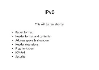
0 4 12 16 24 31 V ersion T rafficClass FlowLabel PayloadLen NextHeader HopLimit SourceAddress DestinationAddress Next header/data IPv6 Datagram 4: Network Layer
IPv6 Base Header Format • VERS = IPv6 • TRAFFICE CLASS: specifies the routing priority or QoS requests • FLOW LABEL: to be used by applications requesting performance guarantees • PAYLOAD LENGTH: like IPv4’s datagram length, but doesn’t include the header length like IPv4 • NEXT HEADER: indicates the type of the next object in the datagram either type of extension header or type of data • HOP LIMIT: like IPv4’s TimeToLive field but named correctly • NO CHECKSUM (processing efficiency) 4: Network Layer
Address Space • 32 bits versus 128 bits - implications? • 4 billiion vesus 3.4 X1038 • 1500 addresses per square foot of the earth surface 4: Network Layer
Addresses • Still divide address into prefix that designates network and suffix that designates host • But no set classes, boundary between suffix and prefix can fall anywhere (CIDR only) • Prefix length associated with each address 4: Network Layer
Addresses Types • Unicast: delivered to a single computer • Multicast: delivered to each of a set of computers (can be anywhere) • Conferencing, subscribing to a broadcast • Anycast: delivered to one of a set of computers that share a common prefix • Deliver to one of a set of machines providing a common servicer 4: Network Layer
Address Notation • Dotted sixteen? • 105.67.45.56.23.6.133.211.45.8.0.7.56.45.3.189.56 • Colon hexadecimal notation (8 groups) • 69DC:8768:9A56:FFFF:0:5634:343 • Or even better with zero compression (replace run of all 0s with double ::) • Makes host names look even more attractive huh? 4: Network Layer
Special addresses • Ipv4 addresses all reserved for compatibility • 96 zeros + IPv4 address = valid IPv6 address • Local Use Addresses • Special prefix which means “this needn’t be globally unique” • Allow just to be used locally • Aids in autoconfiguration 4: Network Layer
Datagram Format • Base Header + 0 to N Extension Headers + Data Area 4: Network Layer
Extensible Headers • Why? • Saves Space and Processing Time • Only have to allocate space for and spend time processing headers implementing features you need • Extensibility • When add new feature just add an extension header type - no change to existing headers • For experimental features, only sender and receiver need to understand new header 4: Network Layer
Flow Label • Virtual circuit like behaviour over a datagram network • A sender can request the underlying network to establish a path with certain requirements • Traffic class specifies the general requirements (ex. Delay < 100 msec.) • If the path can be established, the network returns an identifier that the sender places along with the traffic class in the flow label • Routers use this identifier to route the datagram along the prearranged path 4: Network Layer
ICMPv6 • New version of ICMP • Additional message types, like “Packet Too Big” • Multicast group management functions 4: Network Layer
Summary like IPv6 • Connectionless (each datagram contains destination address and is routed seperately) • Best Effort (possibility for virtual circuit behaviour) • Maximum hops field so can avoid datagrams circulating indefinitely 4: Network Layer
Summary New Features • Bigger Address Space (128 bits/address) • CIDR only • Any cast addresses • New Header Format to help speed processing and forwarding • Checksum:removed entirely to reduce processing time at each hop • No fragmentation • Simple Base Header + Extension Headers • Options: allowed, but outside of header, indicated by “Next Header” field • Ability to influence the path a datagram will take through the network (Quality of service) 4: Network Layer
Transition From IPv4 To IPv6 • Not all routers can be upgraded simultaneous • no “flag days” • How will the network operate with mixed IPv4 and IPv6 routers? • Two proposed approaches: • Dual Stack: some routers with dual stack (v6, v4) can “translate” between formats • Tunneling: IPv6 carried as payload n IPv4 datagram among IPv4 routers 4: Network Layer
Dual Stack Approach 4: Network Layer
Tunneling IPv6 inside IPv4 where needed 4: Network Layer
6Bone • The 6Bone: an IPv6 testbed • Started as a virtual network using IPv6 over IPv4 tunneling/encapsulation • Slowly migrated to native links fo IPv6 transport • RFC 2471 4: Network Layer
Recent History • First blocks of IPv6 addresses delegated to regional registries - July 1999 • 10 websites in the .com domain that can be reached via an IPv6 enhanced client via an IPv6 TCP connection (http://www.ipv6.org/v6-www.html) - it was 5 a year ago (not a good sign?) 4: Network Layer
IPv5? • New version of IP temporarily named “IP - The Next Generation” or IPng • Many competing proposals; name Ipng became ambiguous • Once specific protocol designed needed a name to distinguish it from other proposals • IPv5 has been assigned to an experimental protocol ST 4: Network Layer
Network Address Translation (NAT) 4: Network Layer
Background • IP defines private intranet address ranges • 10.0.0.0 - 10.255.255.255 (Class A) • 172.16.0.0 - 172.31.255.255 (Class B) • 192.168.0.0 - 192.168.255.255 (Class C) • Addresses reused by many organizations • Addresses cannot be used for communication on Internet 4: Network Layer
Problem Discussion • Hosts on private IP networks need to access public Internet • All traffic travels through a gateway to/from public Internet • Traffic needs to use IP address of gateway • Conserves IPv4 address space • Private IP addresses mapped into fewer public IP addresses • Will this beat Ipv6? 4: Network Layer
All Private Network hosts must use the gateway IP address Public network IP address, globally unique Same private network IP addresses may be used by many organizations Scenario 128.32.32.68 BMRC Server Public Internet 24.1.70.210 Gateway 10.0.0.1 10.0.0.2 10.0.0.4 10.0.0.3 Host A Private Network 4: Network Layer
Network Address Translation Solution • Special function on gateway • IP source and destination addresses are translated • Internal hosts need no changes • No changes required to applications • TCP based protocols work well • Non-TCP based protocols more difficult • Provides some security • Hosts behind gateway difficult to reach • Possibly vulnerable to IP level attacks 4: Network Layer
Server TCP Connection 1 TCP Connection 1 NAT Example NAT Gateway Address Translator 128.32.32.68 bmrc.berkeley.edu 4: Network Layer
SYN flag indicates a new TCP connection SYN SYN, ACK ACK Packet 0:50 ACK 0:50 FIN FIN, ACK TCP Protocol Diagram Client Server IP Header . . . . . Checksum Source IP Address Destination IP Address . . . . . TCP Header Source Port Number Dest Port Number Sequence Number . . . . . 4: Network Layer
1. Host tries to connect to web server at 128.32.32.68. It sends out a SYN packet using its internal IP address, 10.0.0.3. 2. NAT gateway sees SYN flag set, adds new entry to its translation table. It then rewrites the packet using gateway’s external IP address, 24.1.70.210. Updates the packet checksum. Server Internet 2 PROTO SADDR DADDR SPORT DPORT FLAGS CKSUM PROTO SADDR DADDR SPORT DPORT FLAGS CKSUM PROTO SADDR DADDR SPORT DPORT FLAGS CKSUM TCP 10.0.0.3 128.32.32.68 1049 80 SYN 0x1636 TCP 24.1.70.210 128.32.32.68 40960 80 SYN 0x2436 TCP 128.32.32.68 24.1.70.210 80 40960 SYN, ACK 0x8041 1 3 4 PROTO SADDR DADDR SPORT DPORT FLAGS CKSUM TCP 128.32.32.68 10.0.0.3 80 1049 SYN, ACK 0x7841 4. NAT gateway looks in its translation table, finds a match for the source and destination addresses and ports, and rewrites the packet using the internal IP address. 3. Server responds to SYN packet with a SYN,ACK packet. The packet is sent to the NAT gateway’s IP address. TCP NAT Example NAT Gateway 128.32.32.68 10.0.0.1 24.1.70.210 10.0.0.3 NAT Translation Table Client Server IPAddr Port IPAddr Port NATPort 10.0.0.3 1049 128.32.32.68 80 40960 . . . .. . . . .. . . 4: Network Layer
NAT Gateway (Virtual Server) Server Server Server Server Load Balancing Servers with NAT • Single IP address for web server • Redirects workload to multiple internal servers Public Internet Private Intranet 4: Network Layer
Load Balancing Networks with NAT Service Provider 1 NAT Gateway Private Intranet Network X Service Provider 2 • Connections from Private Intranet split across Service Providers 1 and 2 • Load balances at connection level • Load balancing at IP level can cause low TCP throughput 4: Network Layer
NAT Discussion • NAT works best with TCP connections • NAT breaks End-to-End Principle by modifying packets • Problems • Connectionless UDP (Real Audio) • ICMP (Ping) • Multicast • Applications use IP addresses within data stream (FTP) • Need to watch/modify data packets 4: Network Layer
MobileIP 4: Network Layer
MobileIP • Goal: Allow machines to roam around and maintain IP connectivity • Problem: IP addresses => location • This is important for efficient routing • Solutions? • DHCP? • ok for relocation but not for ongoing connections • Dynamic DNS (mobile nodes update name to IP address mapping as they move around)? • ok for relocation but not for ongoing connections 4: Network Layer
Mobile IP • Allows computer to roam and be reachable • Basic architecture • Home agent (HA) on home network • Foreign agent (FA) at remote network location • Home and foreign agents tunnel traffic • Non-optimal data flow 4: Network Layer
MobileIP • Mobile nodes have a permanent home address and a default local router called the “home agent” • The router nearest a nodes current location is called the “foreign agent” • Register with foreign agent when connect to network • Located much like the DHCP server 4: Network Layer
Forwarding Packets • Home agent impersonates the mobile host by changing the mapping from IP address to hardware address (“proxy ARP”) • Sends any packets destined for mobile host on to the foreign agent with IP encapsulation • Foreign agent strips off and does a special translation of the mobile nodes IP address to its current hardware address 4: Network Layer
1. The Mobile Node registers itself with the Foreign Agent on the Foreign Subnet. The Foreign Agent opens an IP-IP tunnel to the Home Agent. The Home Agent begins listening for packets sent to 169.229.2.98. Register 2. The Fixed Node initiates a connection to the Mobile Node. It sends packets to the Mobile Node’s home IP address, 169.229.2.98. The packets are routed to the Home Subnet. 3. The Home Agent receives them, encapsulates them in IP-IP packets, and it sends them to the Foreign Agent. Encapsulated packets are addressed to 18.86.0.253. 4. The Foreign Agent decapsulates the IP-IP packets, and it sends them out on the Foreign Subnet. These packets will be addressed to 169.229.2.98. 5. The Mobile Node receives the packets, and it sends responses directly to the Fixed Node at 128.95.4.112. Mobile IP Example Foreign Agent Mobile Node 169.229.2.98 18.86.0.253 Foreign Subnet Fixed Node Internet 128.95.4.112 Home Subnet Home Agent 169.229.2.97 4: Network Layer
Avoiding the Foreign Agent • Mobile host can also obtain a new IP address on the remote network and inform the home agent • The home agent can then resend the packet to the new IP address 4: Network Layer
Optimizations • What if two remote hosts are temporarily close together • If they want to send traffic to each other, why should it have to go all the way to their home agents and back again • Optimizations exist to allow the sending node to learn and cache the current location of a recipient to avoid this problem 4: Network Layer